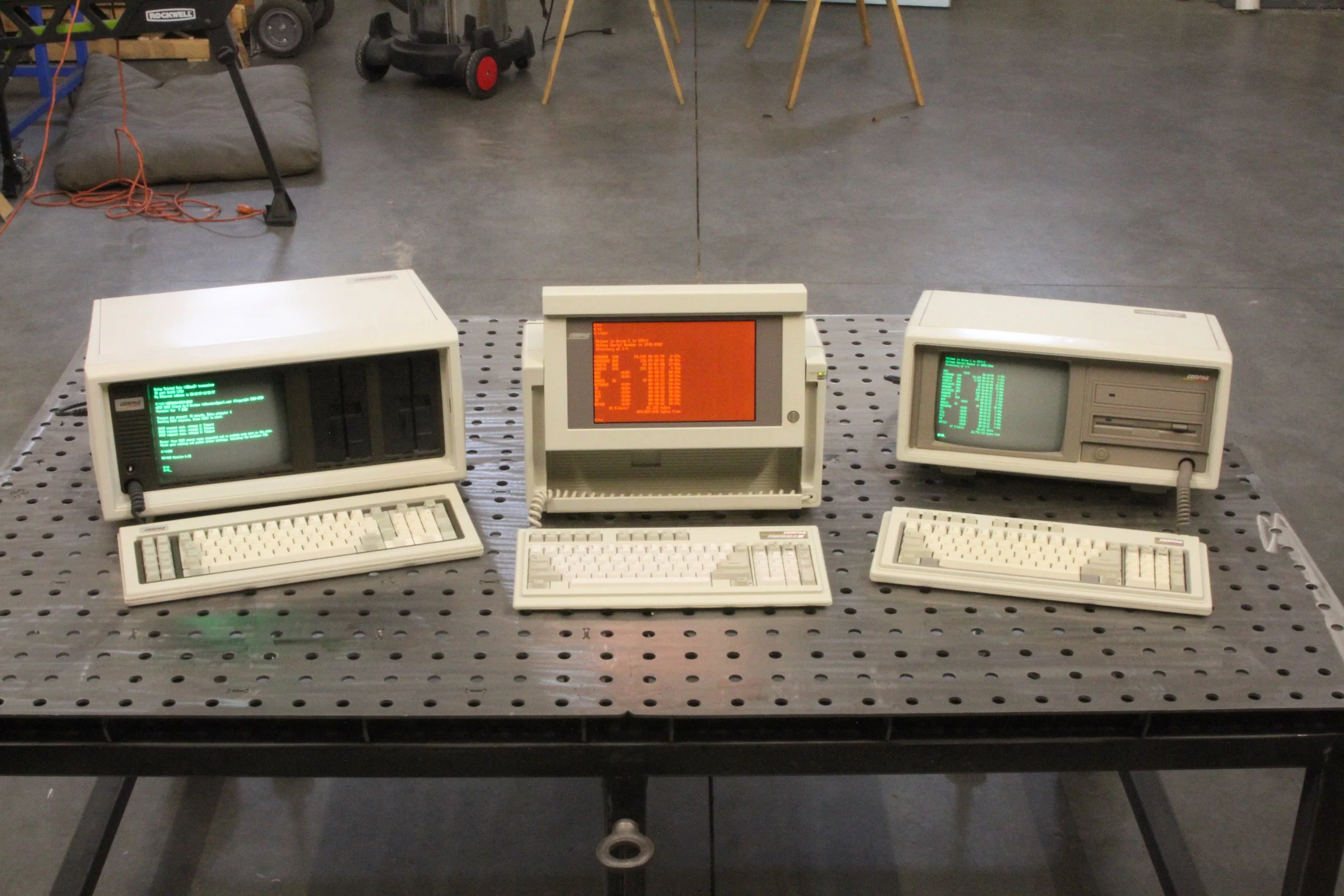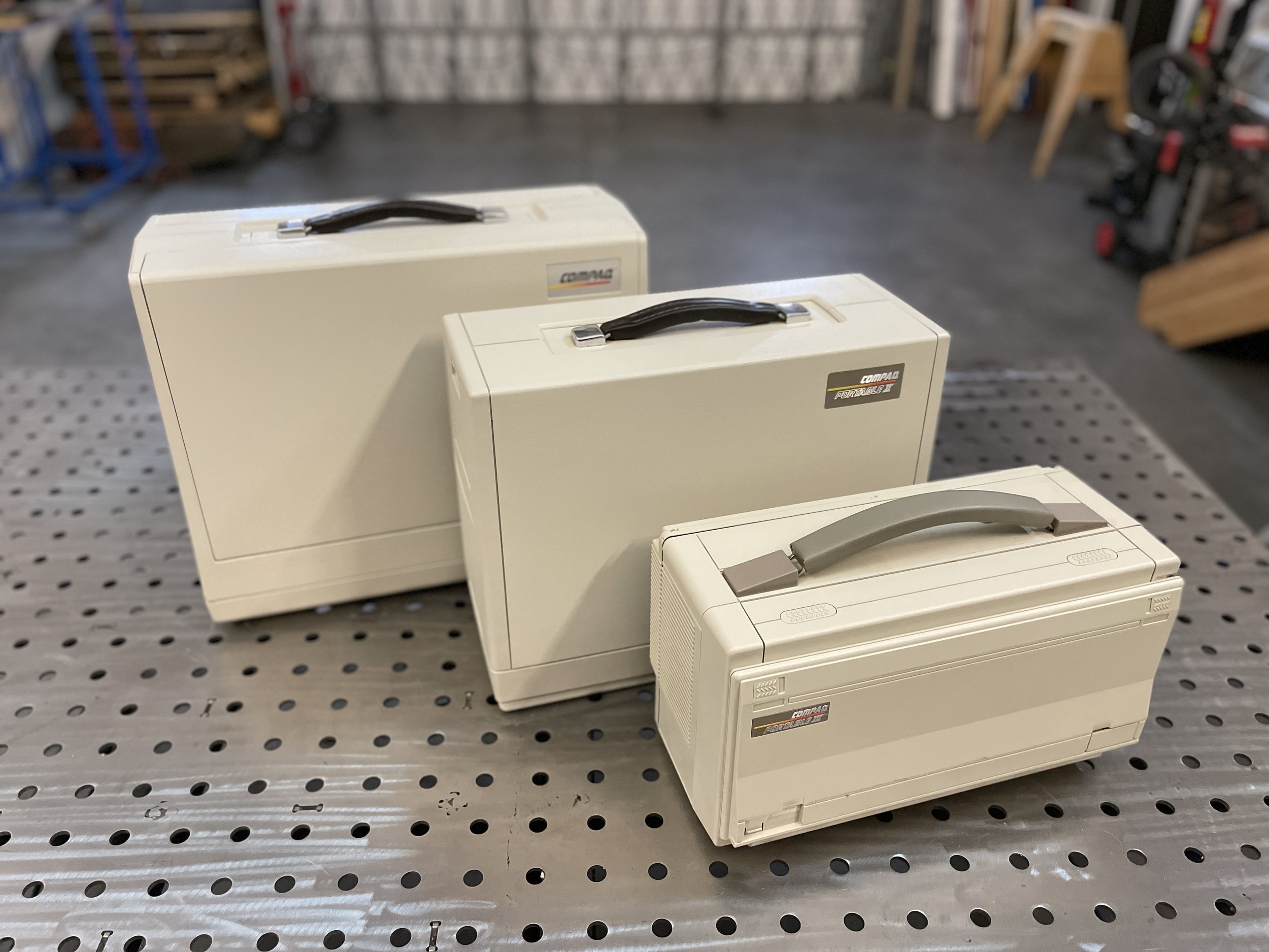
Compaq Portable III
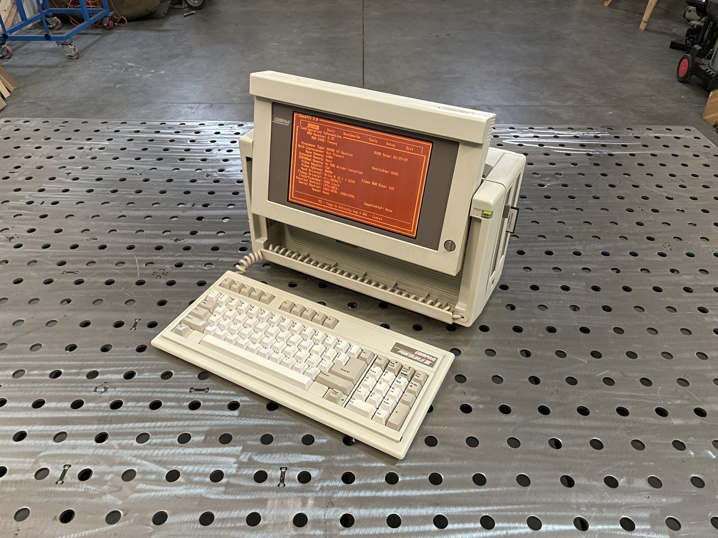
The Compaq Portable III was released in 1987. It was much smaller than the Compaq Portable II that, proceeded it by a year. This Compaq Portable III is the Model 2 that came with a 12Mhz 80286 processor, 640KB of RAM, optional 80287 math coprocessor, 360K/1.2M floppy diskette drive, and 20M Hard disk. The list price for the model 20 was $4,999. A year later, the Compaq Portable 386 was released utilizing the same design.
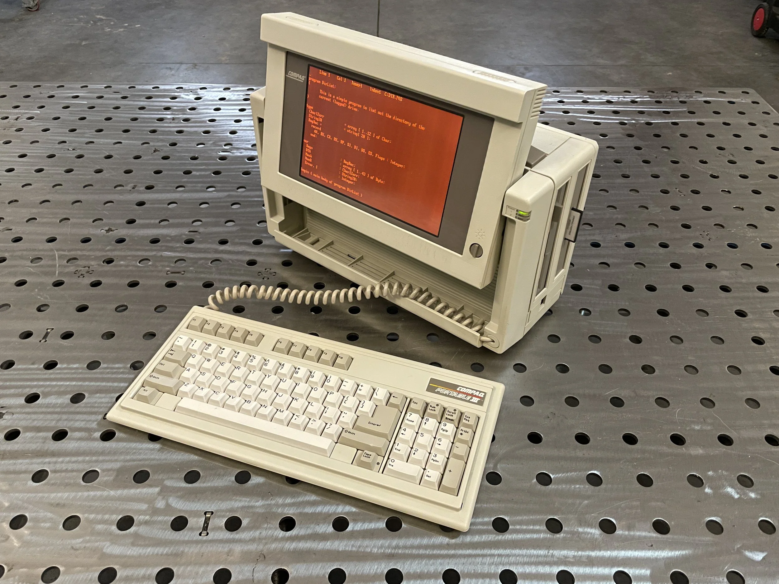
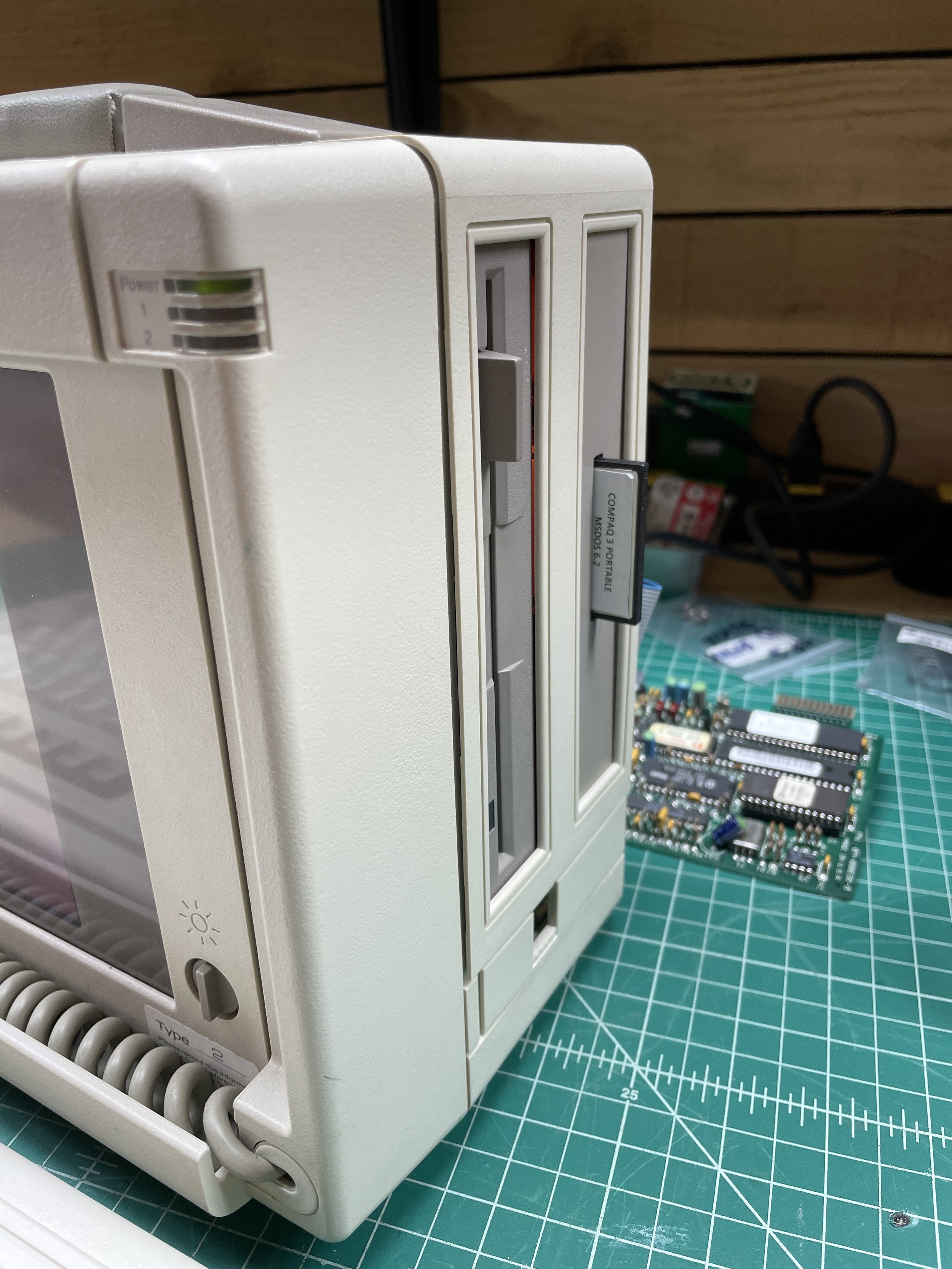
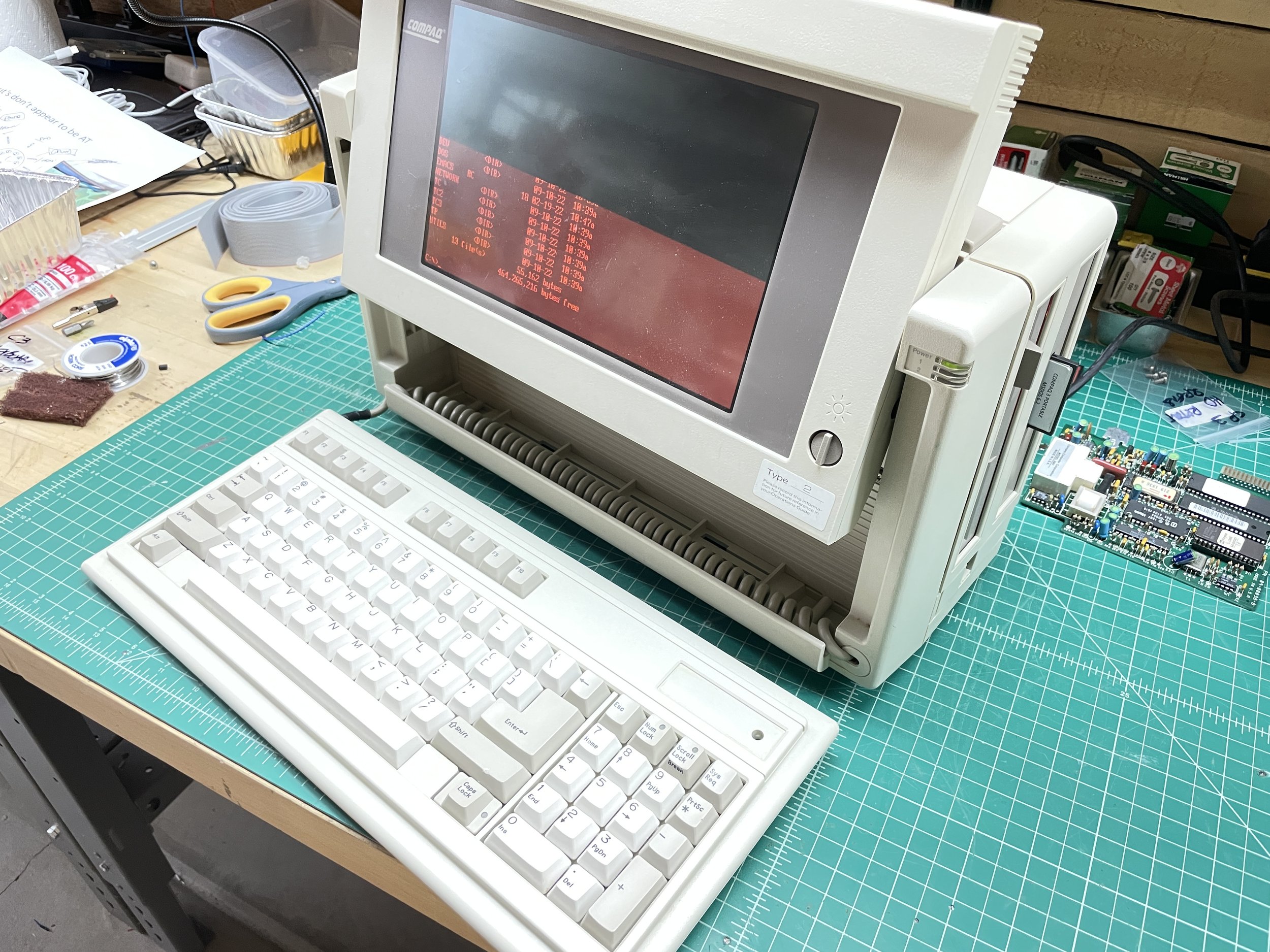
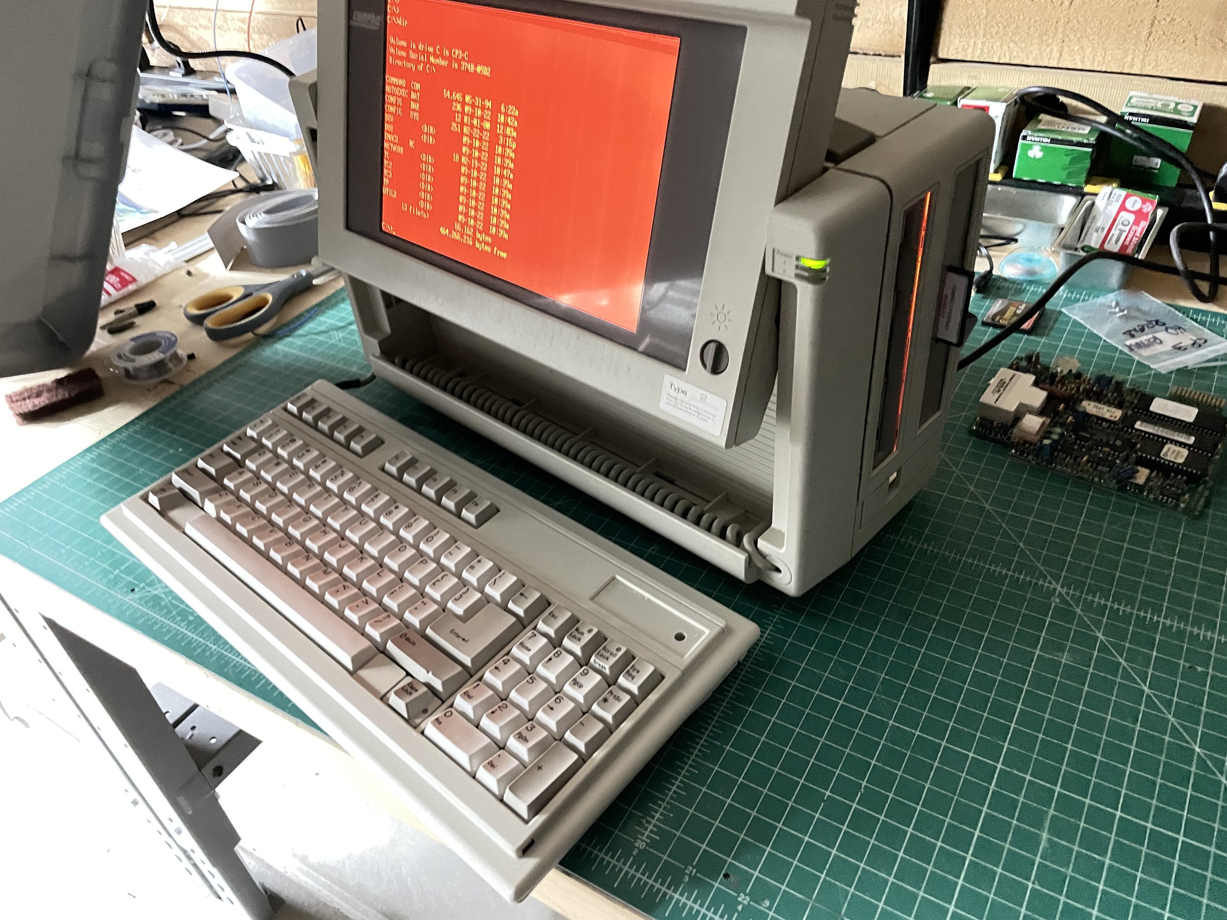
The Compaq Portable III (I'll refer to it as CP3) was a much different design than previous Compaq Portable Models. The most obvious change was a flat 10" Gas Plasma screen in amber/orange. The screen is fast and bright. There is always a brightness to the background, which is unfortunate, but the screen is still quite readable. Compaq changed the DOS font to better suit the screen.
The CP3 had no internal ISA slots. A sidecar expansion unit could be attached that would add 2 ISA slots, but that negates that small portable size and weight advantage.
The CP3 ran only on AC power like the machines that came before it. The power supply is a bit unusual in that it has a 200V DC output for the Plasma Display.

Acquisition
I found this CP3 on eBay shortly after I started the CP2 restoration. It had a 20Mb Hard Disk installed that still worked. I believe it was an original Conner Drive. This computer also had a 1200 baud modem specifically designed for a small expansion slot on the side of the computer.
When searching for a CP3, I found that a lot of CP3s and Compaq Portable 386 machines have broken screens. This usually manifests itself as horizontal or vertical lines of pixels that are on all the time. It's probably unlikely that a machine in this state can ever be fixed, much like stuck pixels on modern LED displays. For both reasons, I made it a point to find a working system.
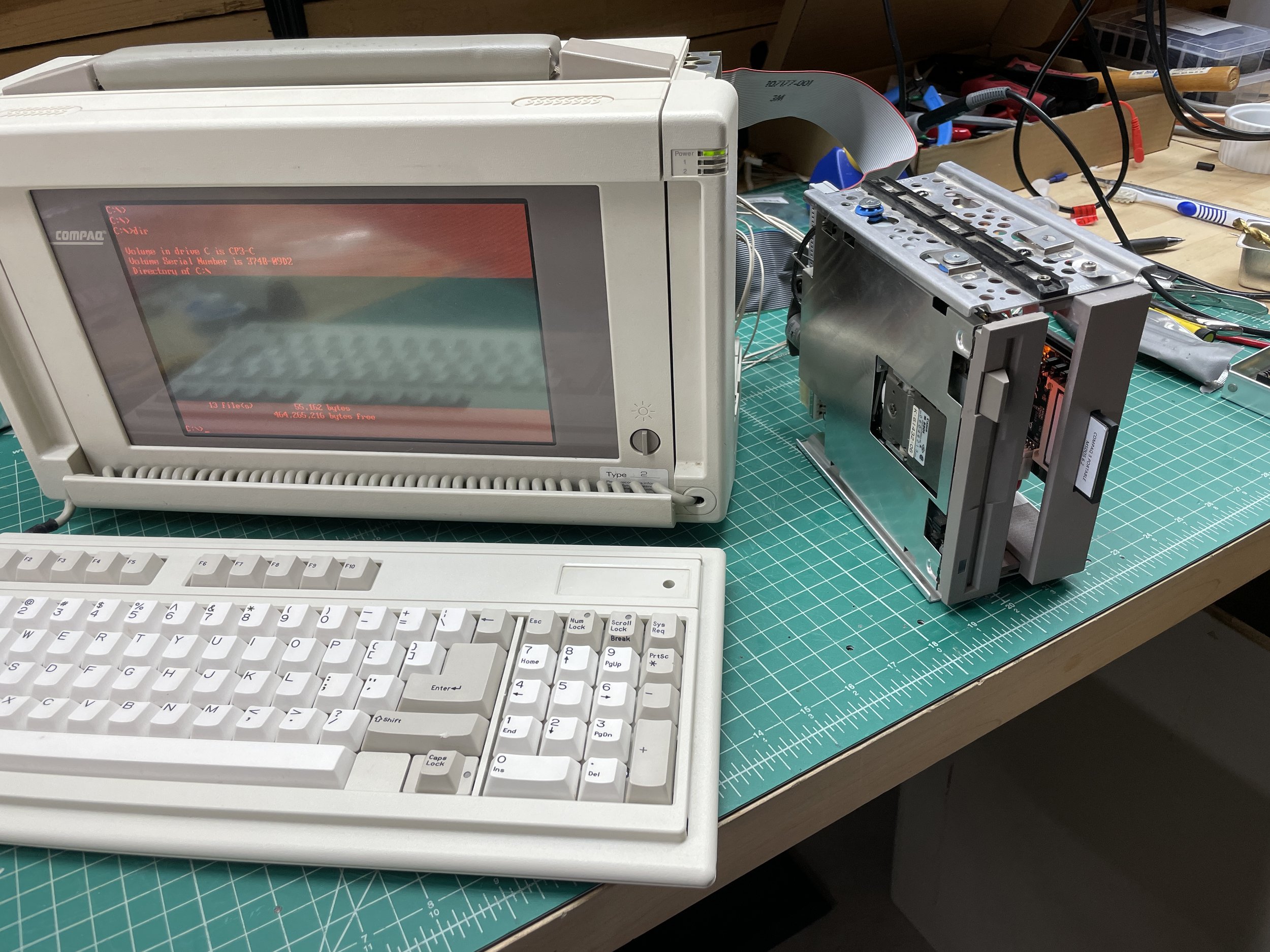
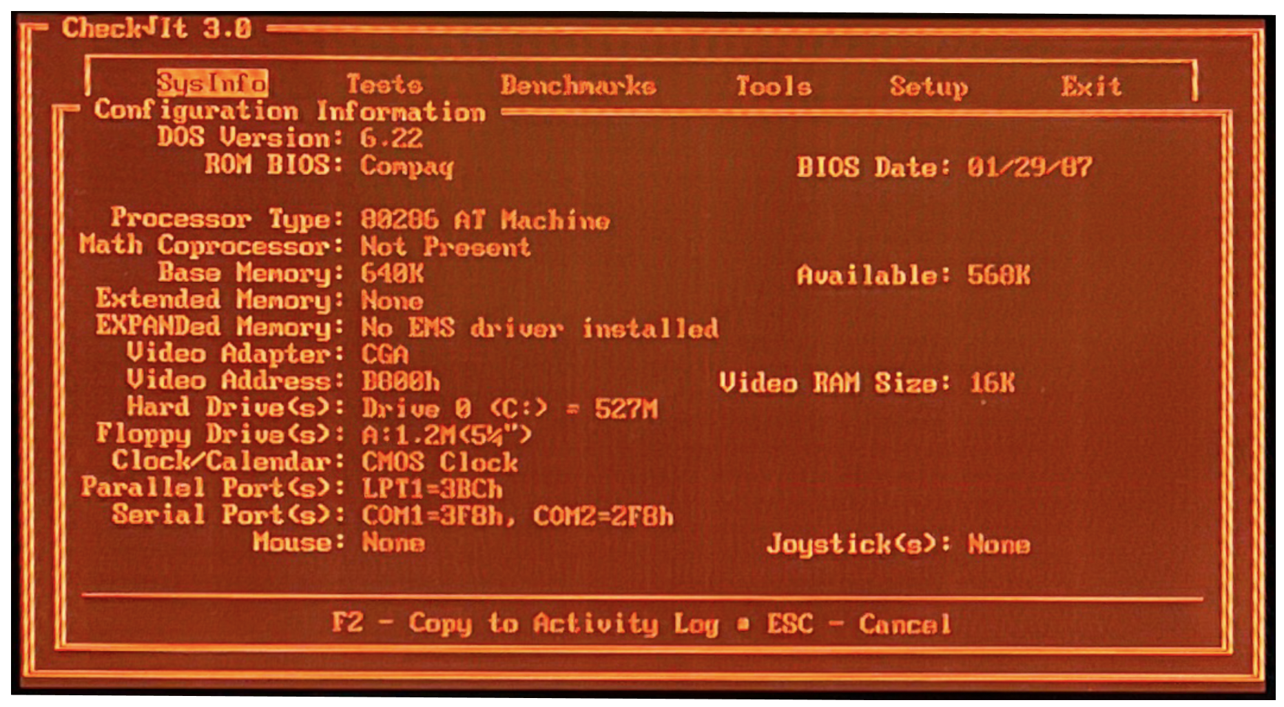
When the computer arrived, it was completely functional and booted up into Compaq DOS 3.3.

Ahh, the Keyboard doesn’t suck, finally!
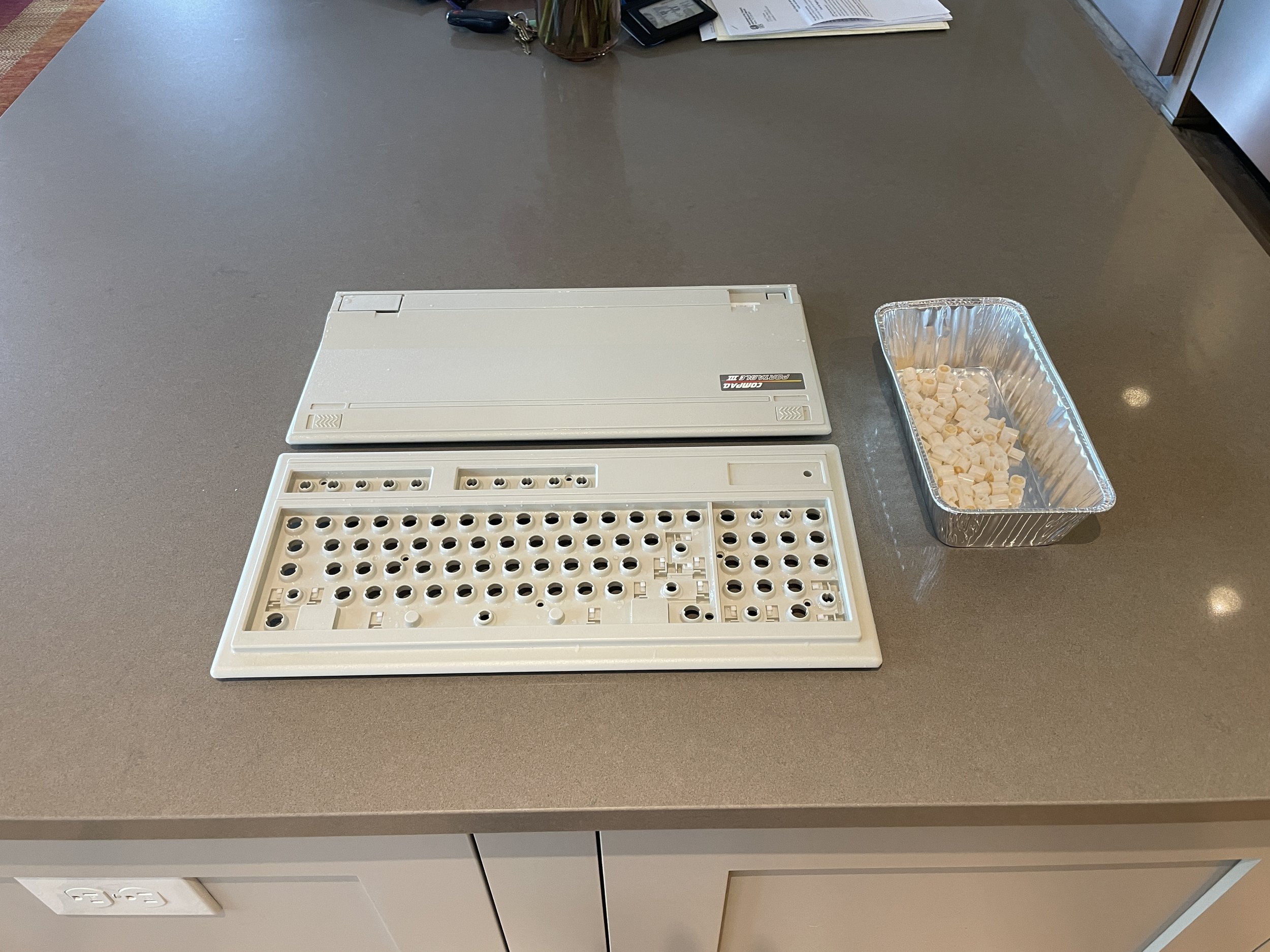
When the computer arrived, the keyboard was extremely yellowed, this is a common problem with the ABS plastic that Compaq used. I fixed this by retrobriting the keycaps. You can read about that on the CP2 restore here.
Much to my delight, the keyboard on the CP3 is very nice to type on. The CP1 and CP2 both used a Keytronics-supplied keyboard that uses Foil-and-foam inserts with rubber domes under the keys providing tactile feedback.
These Keytronics boards are horrible to type on, even after being fixed. You can read about that in the CP1 and CP2 posts.
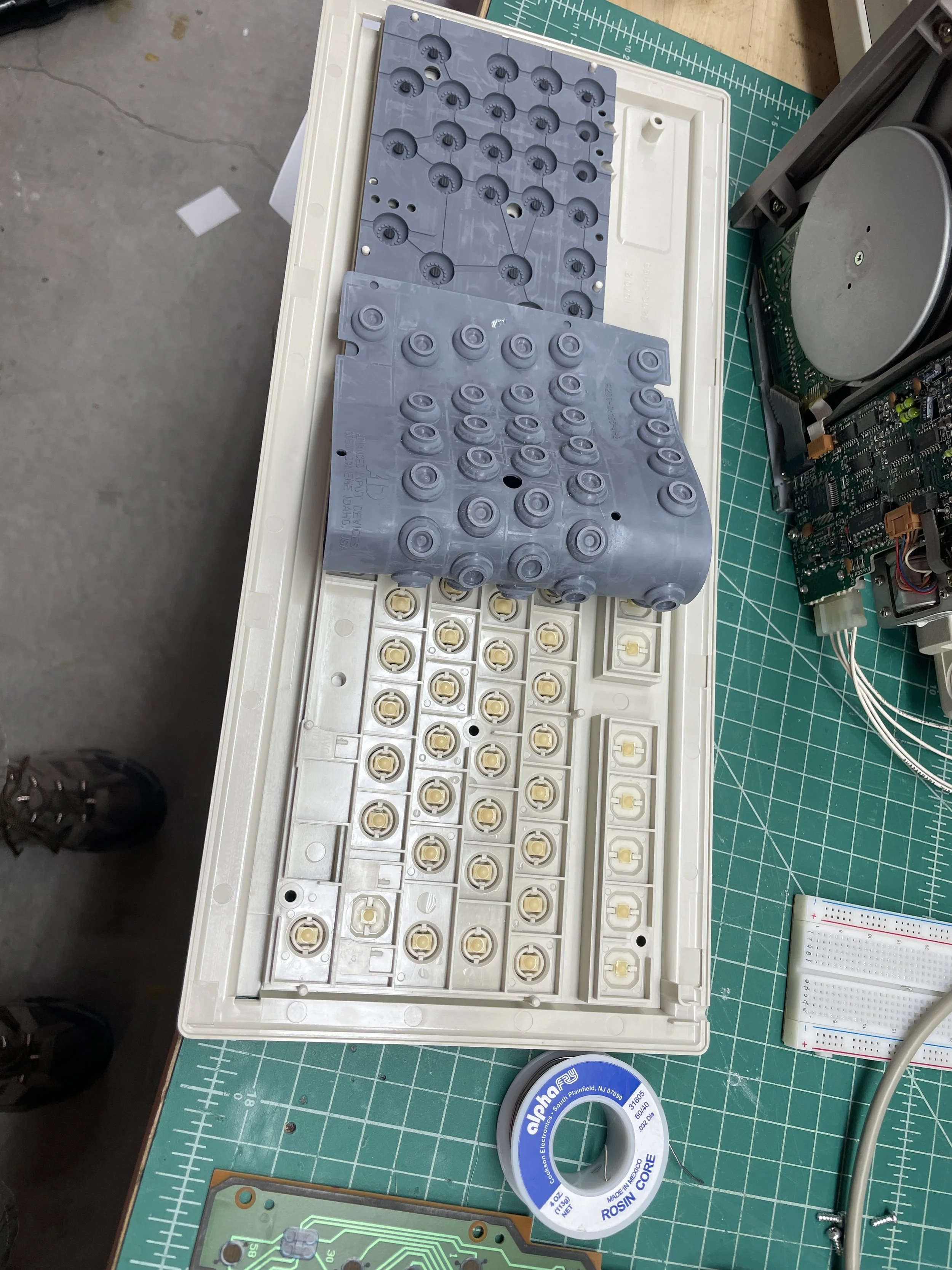
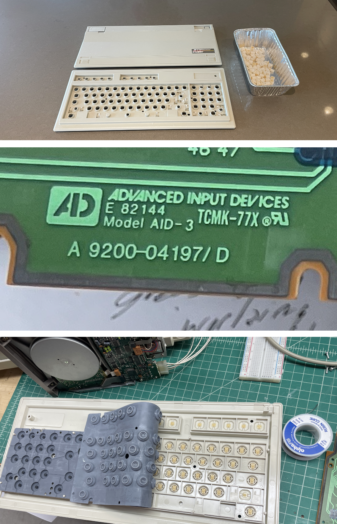
By contrast, the CP3 keyboard was manufactured by Advanced Input Devices and is great. Amazingly Advanced Input is still around today, 40 years later.
Like the Keytronics keyboard, this keyboard is a capacitive design, but removes the foil-and-foam inserts and replaces them with a small carbon pad that touches the PCB board when the rubber dome is depressed. It has a great feel and has stood the test of time. This keyboard was completely functional and needed nothing other than cosmetic work when I got it.
I suspect some people upgraded to the CP3 just for the keyboard, it’s lightyears better.
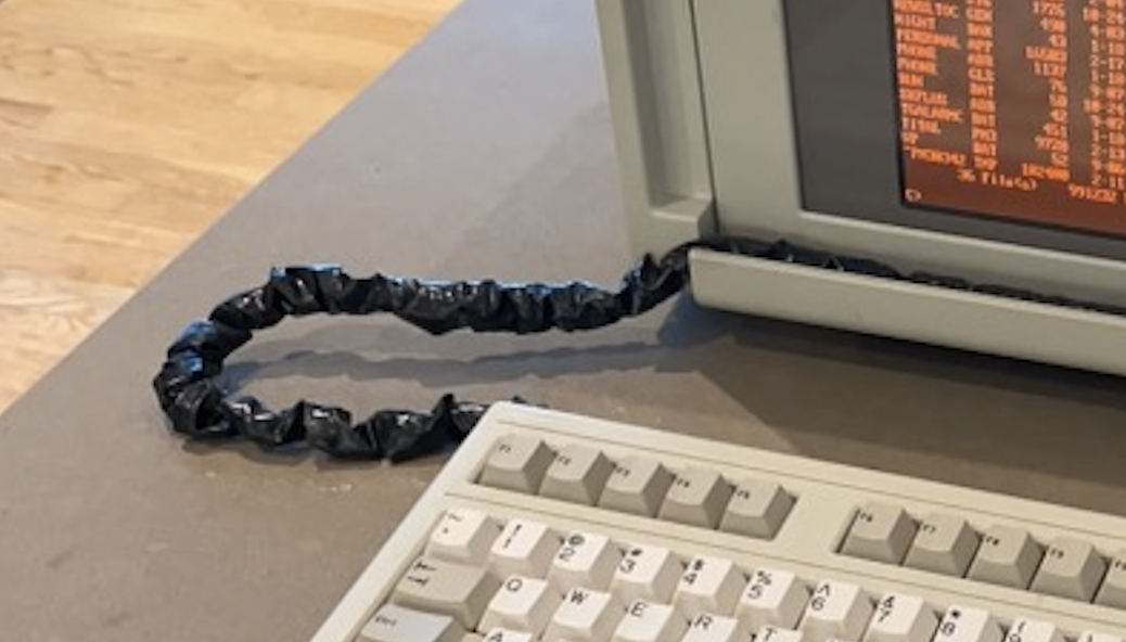
The keyboard cable, however, is another matter. The cable has not stood the test of time. Literally every CP3 you find out there will have a keyboard cable that is brittle, broken, or non-existent. These cables suffered from a total breakdown of the insolation. My machine literally had no insulation left, and the conductors were covered with electrical tape.
I document the arduous replacement process below.

Process
It was obvious a lot of the work was going to involve replacing the hard disk with an ISA2CF board, fixing the keyboard cable, replacing the battery, and devising some way to access the CF card without opening the case. Compaq plastic from this era is pretty brittle, so the less opening and closing, the better after the machine is finished.
First, I removed the back of the case. This is fairly easy as the case is held together with four very long, very skinny machine screws. You do not want to lose these as it's unlikely you could ever find a suitable replacement for them.
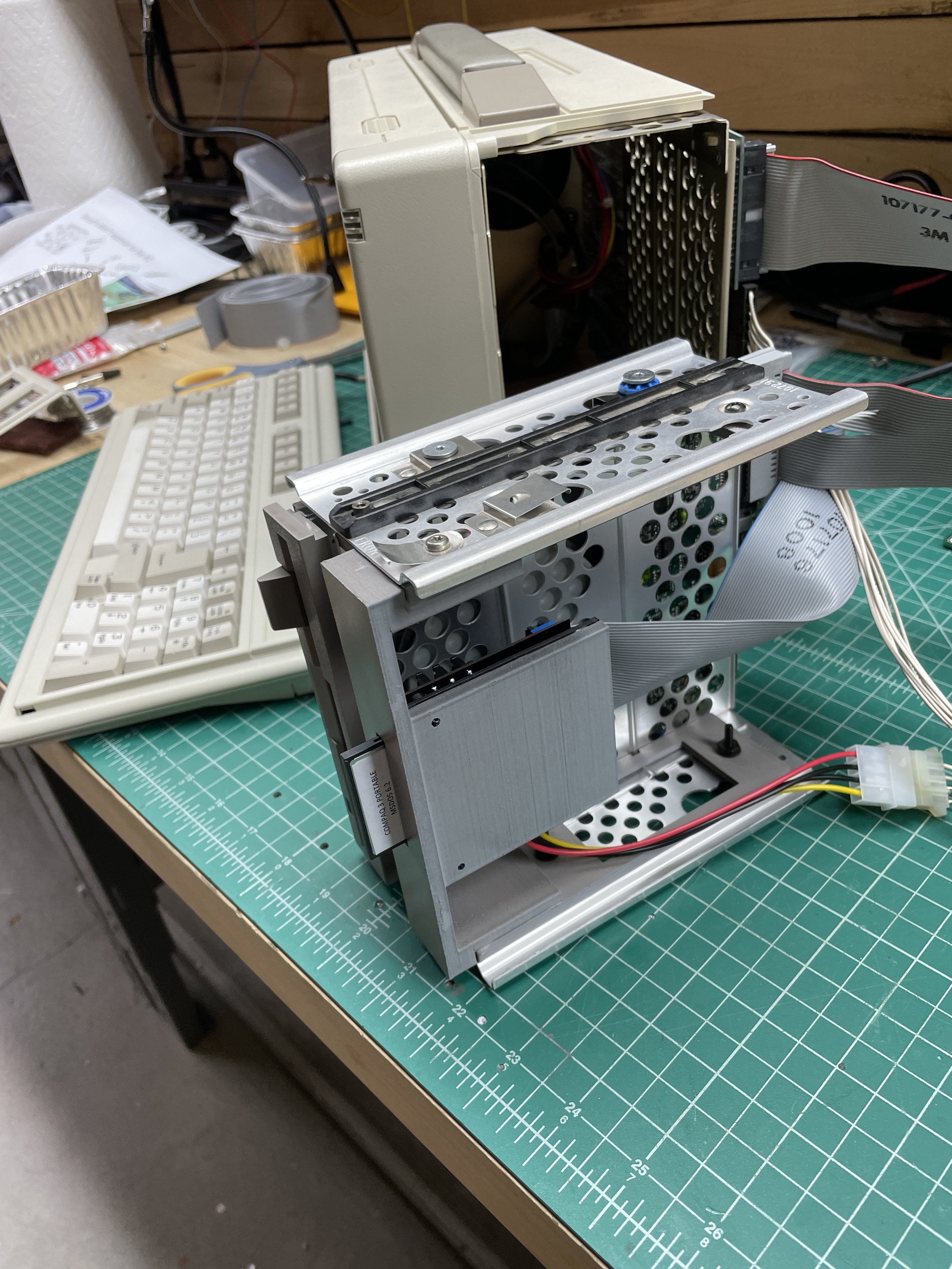
Once removed, the back of the case comes off easily, revealing the motherboard. At this point, you can also remove the side bezel revealing the drive sled containing the floppy drive and hard drive. You can then slide out the drive sled from the side. It's a nice feature that the cables are long enough to allow drive operation with the sled completely removed. I ran the system this way for weeks while doing other work on the system.

I watched a few disassembly videos online before really getting into it. I wanted to look at the power supply, but that appears impossible to do without removing the plasma screen. After watching a video of someone removing the plasma display, I decided it was probably easy to break the display just for a look at the power supply, and I didn't go any further.
I removed all the screws holding the motherboard to the chassis and looked at the underside of the motherboard. I thought this was necessary to access the drive sled, but you can do that simply by removing the top screw on the sled and pulling it out. Realizing this, I put all the motherboard screws back in except one that also holds the modem in place.

Compaq BIOS Settings
As I mentioned in the CP2 post, early Compaq Machines didn't have a BIOS modification user interface program in ROM, like most machines of this era.
Instead, you need to obtain a program that creates bootable floppy diskettes that you can then boot the machine from. I ended up restoring the CP3 and CP2 simultaneously, so I used those same diskettes on the CP3.
To read how to create Compaq Diagnostics Diskettes, read the CP2 Post
Compaq Diagnostics floppy creation utility for 360K floppy diskettes
Compaq Diagnostics floppy creation utility for 720K floppy diskettes

Battery Replacement
My CP3 had a motherboard with a separate battery and a Dallas timekeeper chip. I believe there may be other revisions of this motherboard where Compaq used a single self-contained Dallas Chip with a Battery.
I was happy to see mine was separate, as it's much easier to install a battery than to find a Dallas chip with an embedded battery. I ran into this on my SparcStation IPX, where the Dallas chip had to be cut apart with a Dremel, attaching new wires to stubs inside the Dallas chip. After that, you can connect the wires to a CR2032 battery. A mess, really.
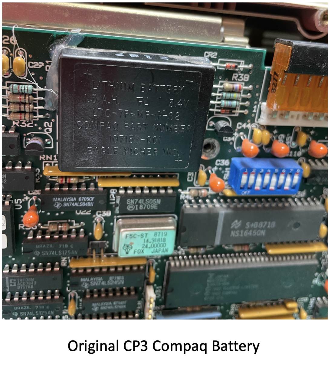
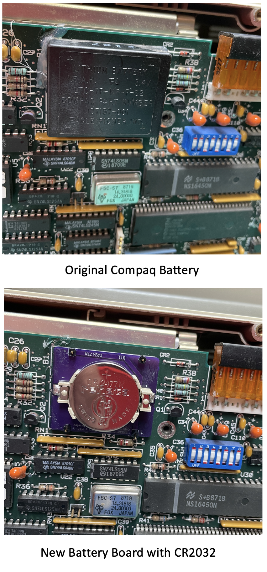
The original battery is fairly large, with four posts that fit into “cups” in the motherboard. Two of the posts are positive leads, and two are negative leads. The battery is not soldered in, but rather the posts just contact the "cups" soldered into holes in the motherboard board. I believe the reason for the four posts is so at least one positive and one negative lead is touching one of the cups. The battery is then held in by hot glue. The NeXT workstation uses a similar design with three legs and a round battery. The NeXT battery is held in with a rubber band attached to the motherboard, which is a novel design.
The battery for the CP3 appeared to no longer be in production, but fortunately, I found an enthusiast-developed design on GitHub for a small circuit board that contains a CR2032 battery holder and header pins that fit perfectly into the motherboard cups. Like the original battery, you can hot glue the assembly onto the motherboard, and you have a fine solution with an easily replaceable battery for the future. The GitHub link has links to have a PCB manufacturer create the board and a link to the Bill Of Materials to order the remaining parts easily.
Here is the link to the GitHub project.
After installing the new battery board, I ran the Compaq Diagnostics BIOS settings program to reset the time and date.
Installing the IDE2CF Card
In nearly all my DOS computers, I install a modern XT-IDE card that provides a compact flash hard disk. I did this on the CP2 as well and disabled the CP2's built-in IDE controller. It was clear that this was not an option with the CP3 as the machine has no IDE slots without adding the expansion sidecar. I really didn't want to add the expansion sidecar, so I had to find a different way to add compact flash storage to the CP3.
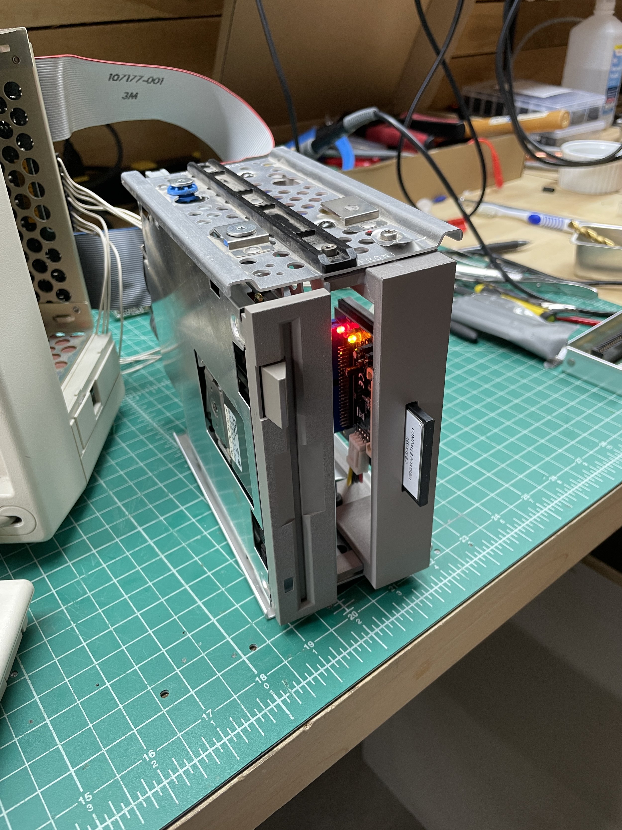
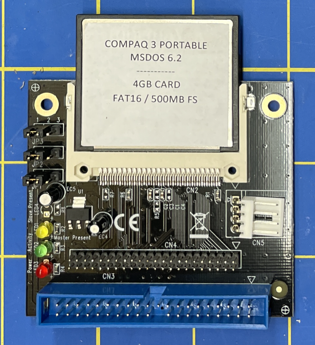
Fortunately, there are IDE2CF cards out there. I bought this card from StarTech and it works great. This is a board that hooks up the IDE cable, the same way a hard disk would connect, but presents a flash card as the hard disk. I usually favor the ISA slot XT-IDE because it's dead simple and installs its own extension BIOS as boot time, allowing more options for sizes of hard disks. However, the IDE2CF card works fine as well.
Using the IDE2CF board on the CP3, you need to assign a "Disk Type" to the IDE2CF that the Compaq supports. As I mentioned in the CP2 post, the "Disk Type" is an index into a table of disk geometry settings.
I had a 4GB CF Card, but the largest Hard Disk the Compaq BIOS understands is a Type 42 Hard Disk which is about 500MB. So that's what I went with. It's large enough, but it is a good example of why the XT-IDE is a better choice for most situations if an ISA slot is available.

Accessing the CF Card
In my other systems where I use XT-IDE cards, it's easy to physically get to the CF Card as it's accessible via the end of the ISA Card. This is not the case with the IDE2CF Board that needs to be adapted to a drive bay.
In my other DOS machines, this wouldn't necessarily be a big deal as I also usually install an ethernet card allowing me to FTP programs to the box. The lack of ISA support made it necessary to mount the IDE2CF card in such a way that I could easily remove it to install new software from my desktop Mac.
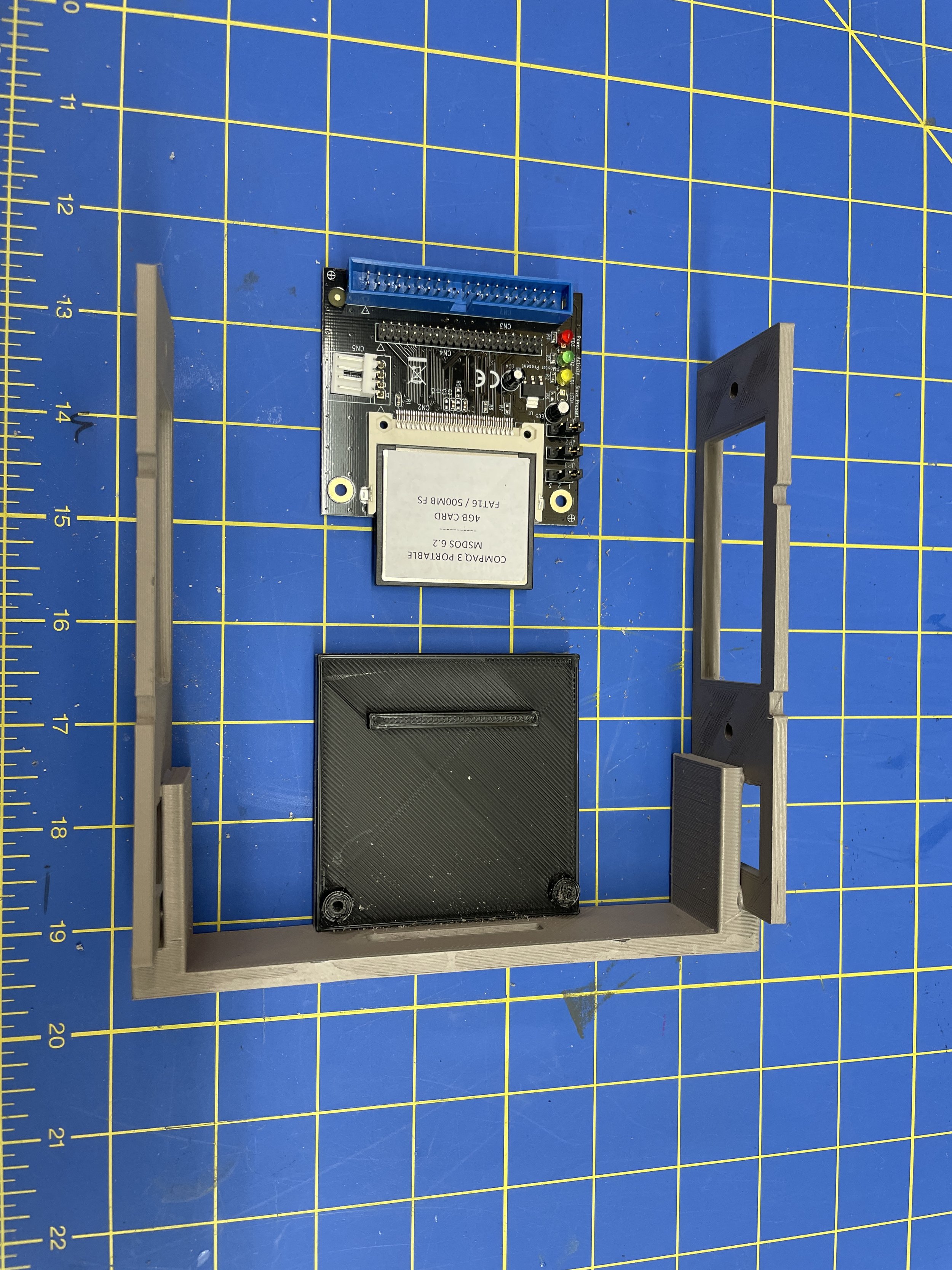
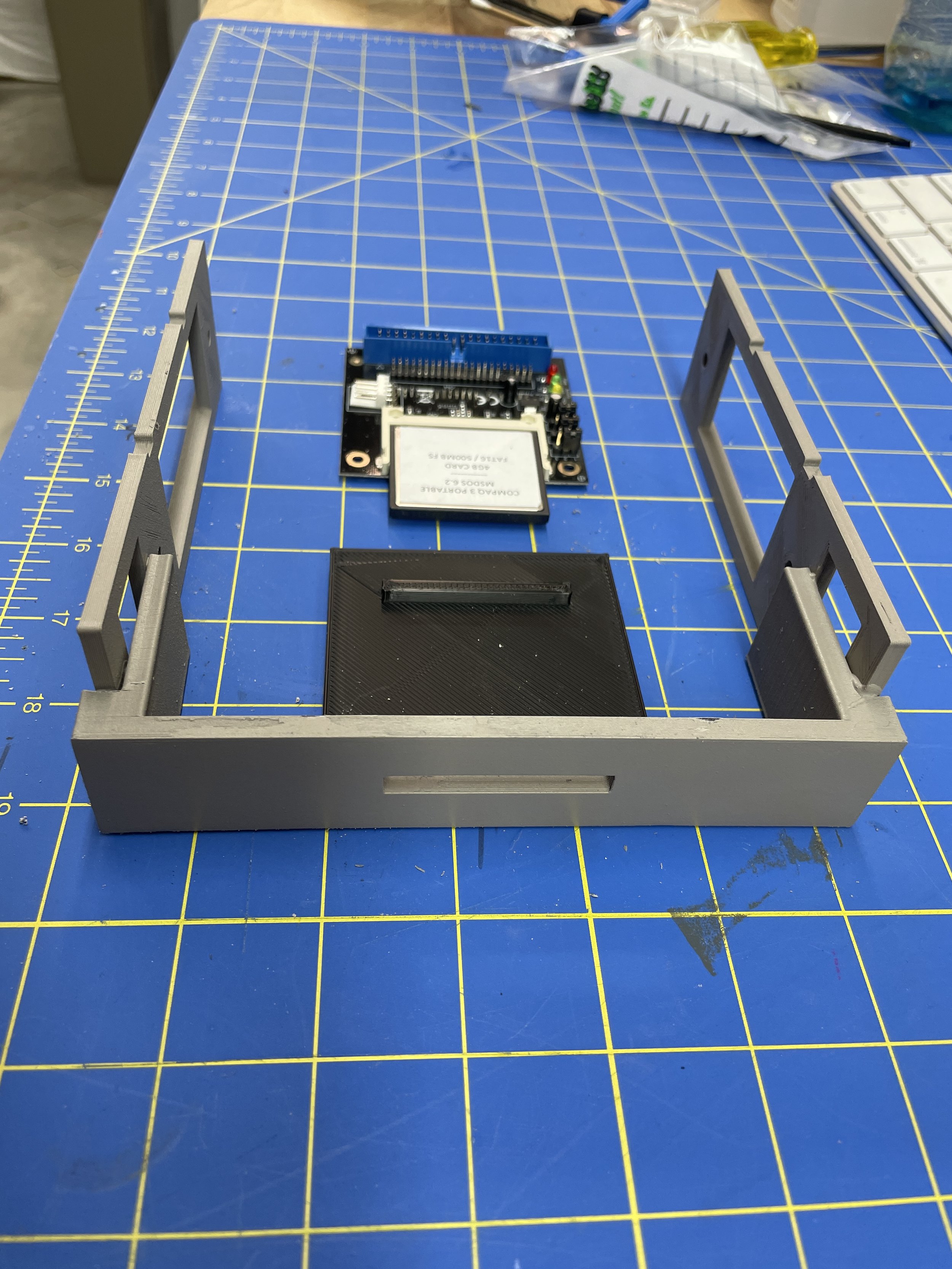
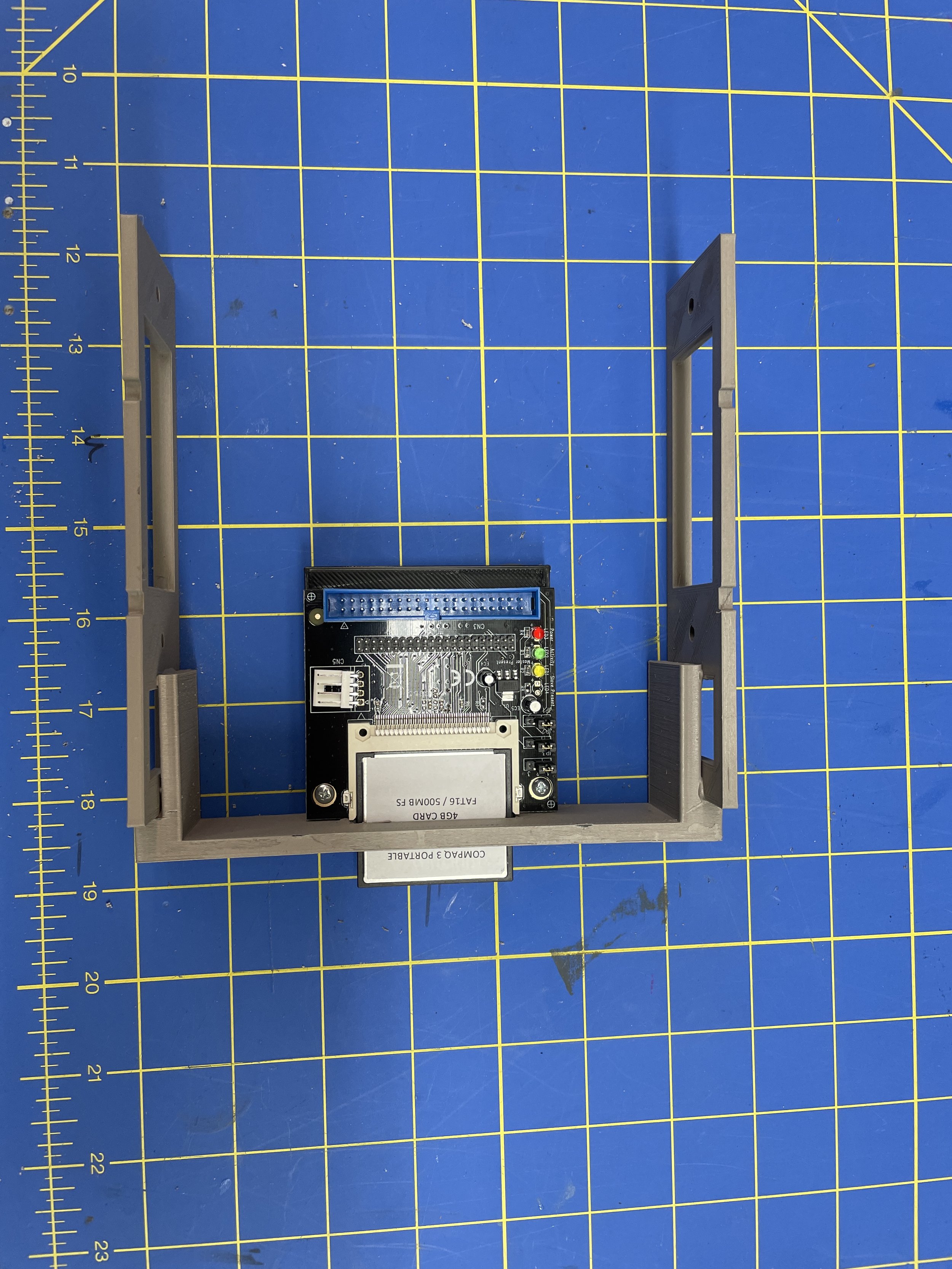
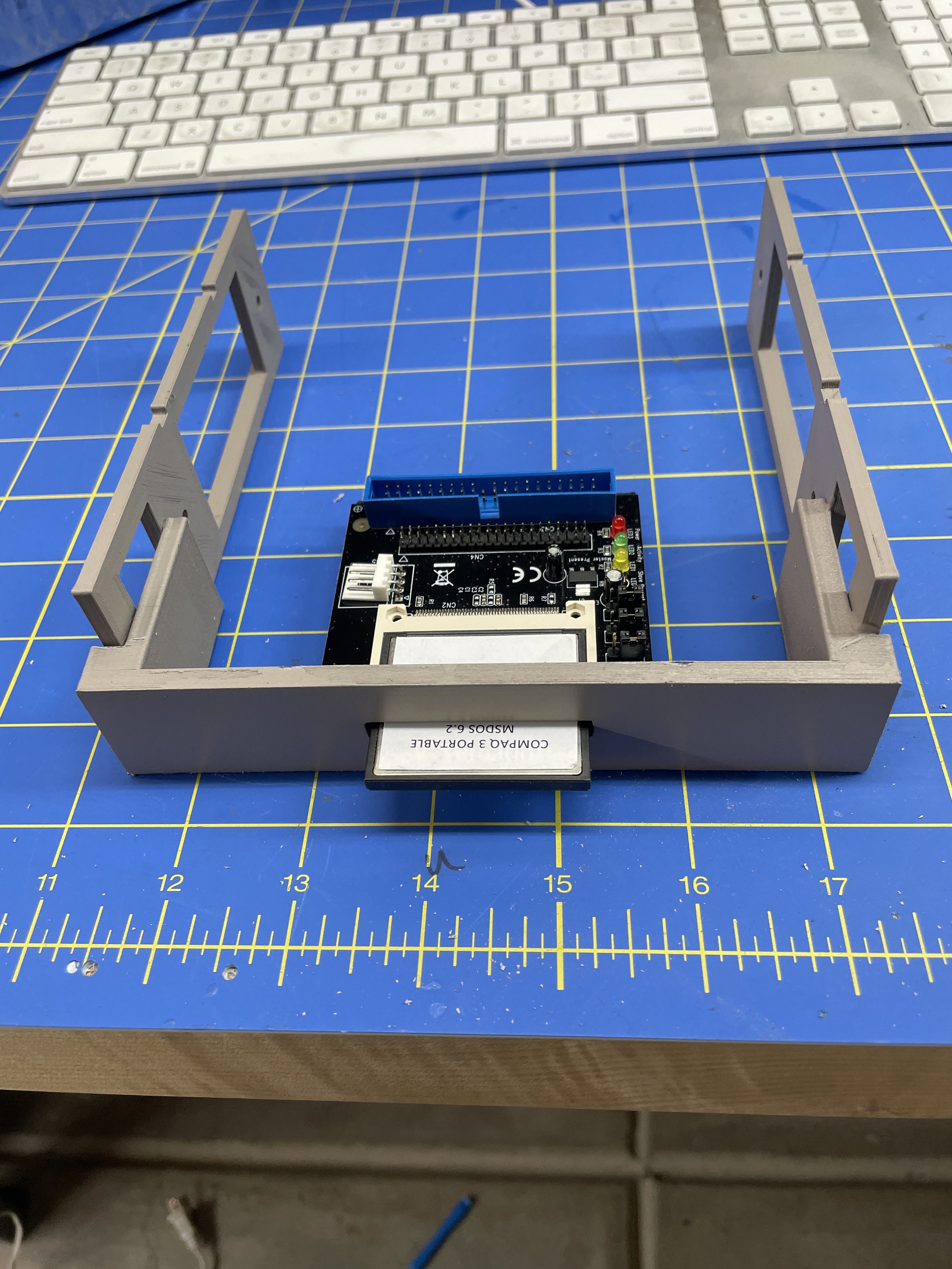
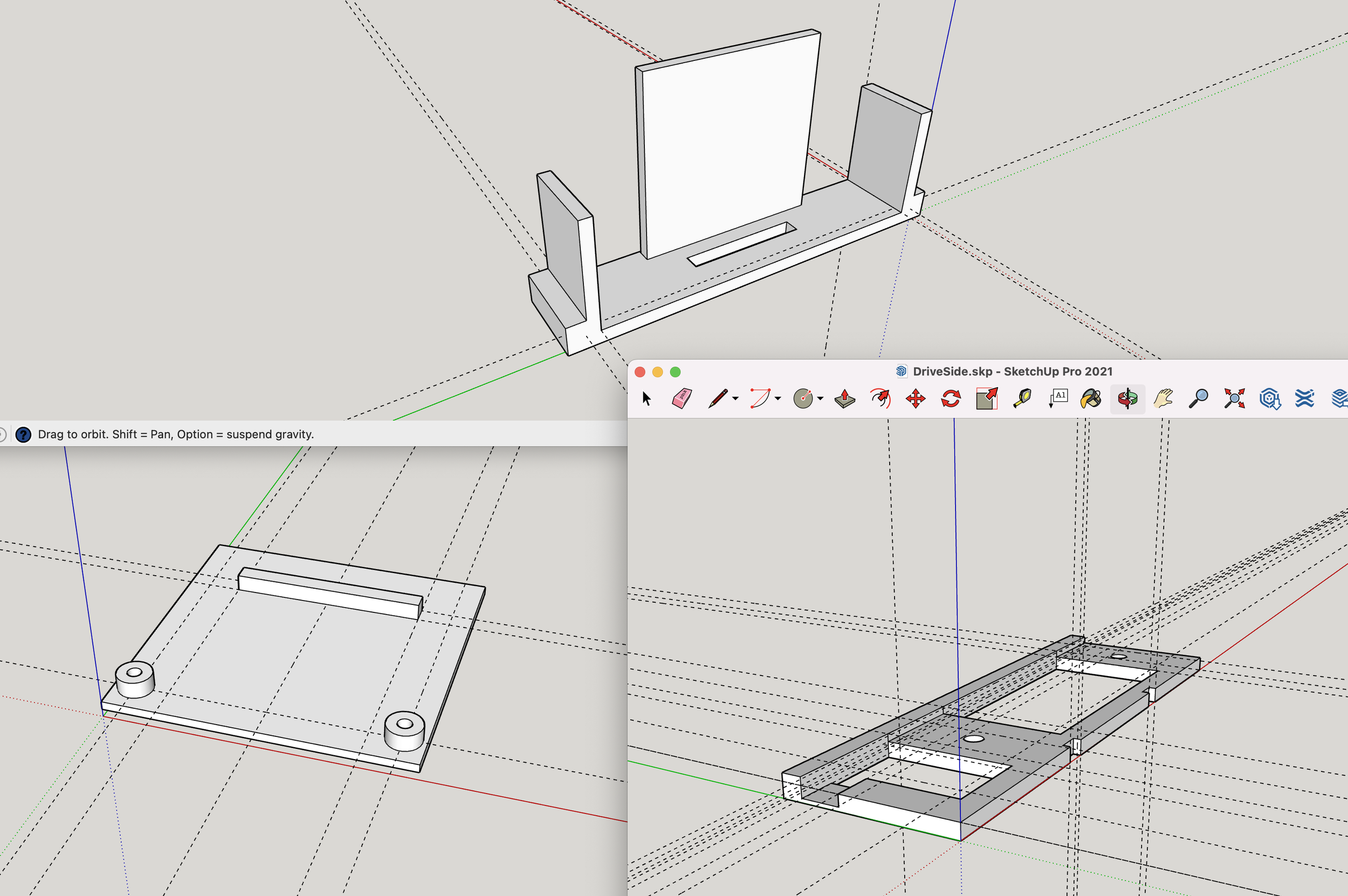
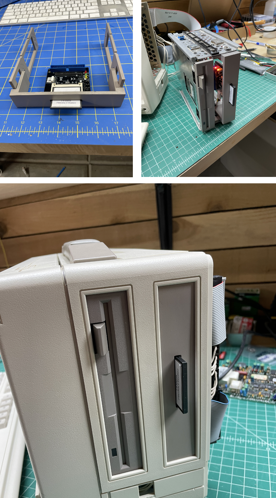
I set out to design a 3D-printed bracket for the IDE2CF card based on the dimensions of the floppy drive. This had the advantage that I had an example device (the floppy drive) to use for gathering correct dimensions from, then transferring to my design in SketchUp. The bracket would then contain the new bezel and would replace the blank bezel in the drive sled cover. After a few iterations, I got the design to fit the sled, fit the board, and be placed exactly correctly in the CP2's side cover. The only thing remaining was the color and texture of the plastic (PLA) of the printed part.
Here are links to the STL files to print your own CF Cardholder. The side piece needs to be printed twice, one reversed, then assembled with JB Weld or similar epoxy.

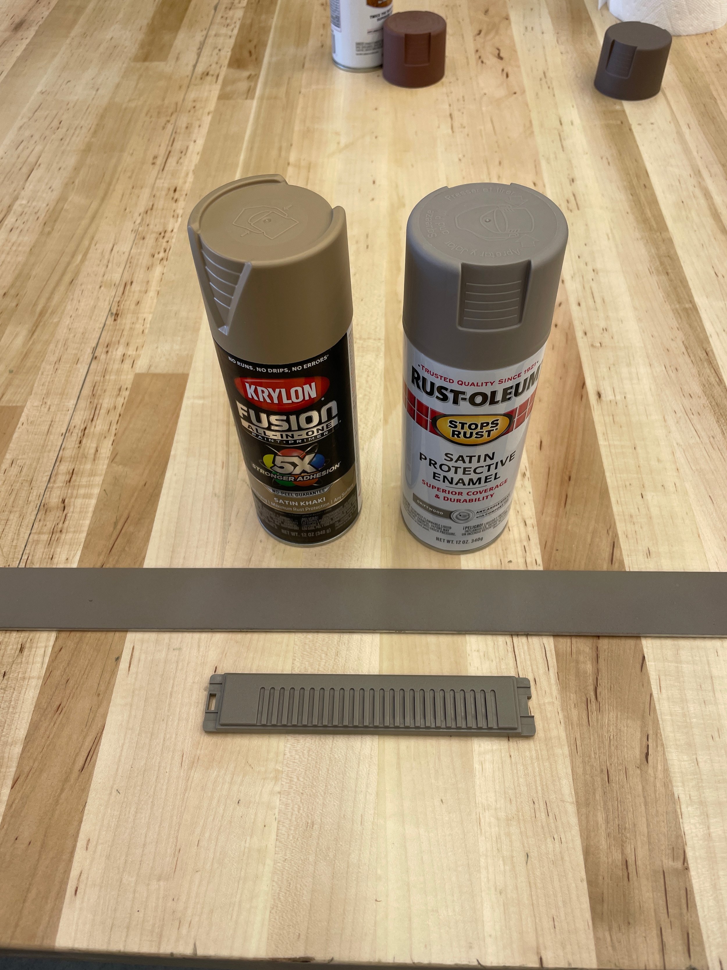
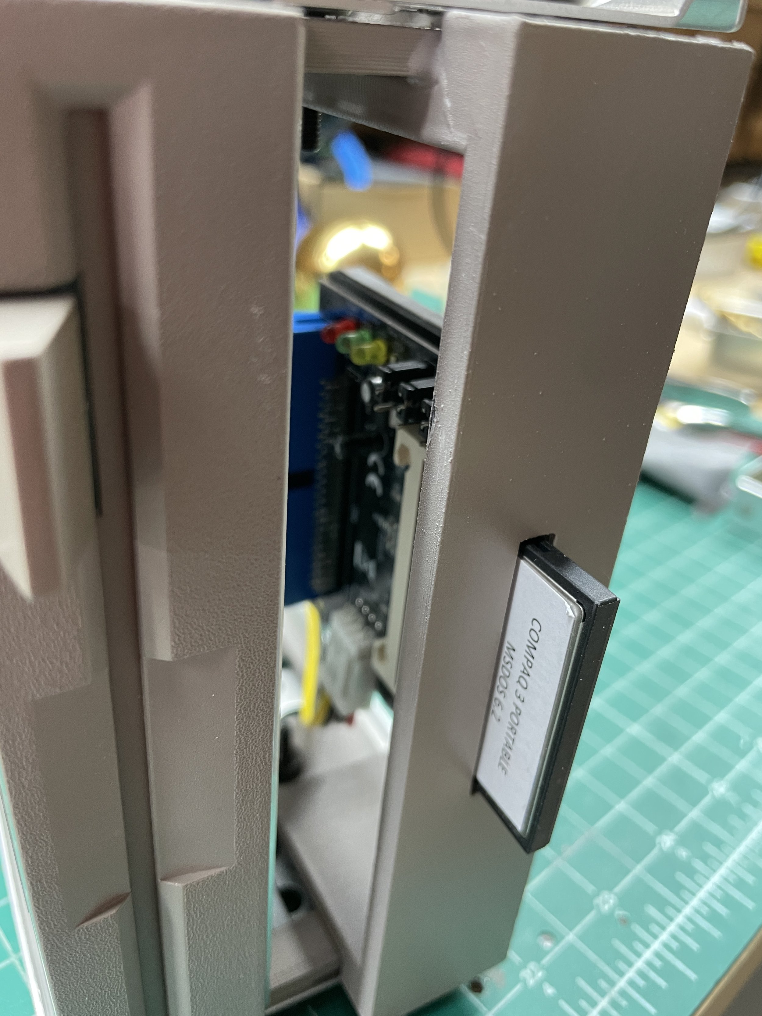
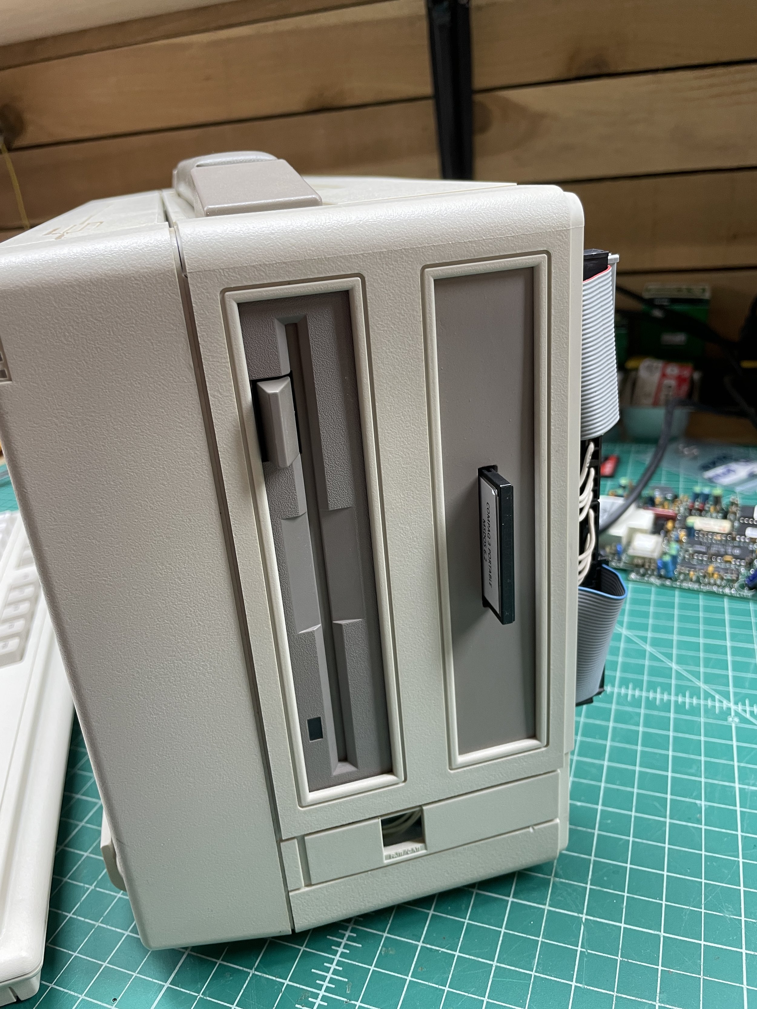
I have had pretty good luck painting custom plastic parts to match some of the older computers in my collection. I did this on my reimagined NeXT LCD Monitor, SGI Indigo Monitor, and SGI Indy monitor. It's a little tricky to find the combinations of paints that get you where you need to go. After some experimentation, I found two colors that, when combined in just the right way, perfectly matched the darker Compaq plastic color.
The two colors are a base of Rust-oleum Satin Driftwood with a few puffs of Krylon Satin Khaki. I generally apply both colors in the same session to allow them to mix on the surface while wet. I then come back the next day to see how it turned out. Once happy with the results, I do several coats of satin clear enamel over the part to create a more tough finish. The photo to right shows the finished color next to the original drive cover bezel on test sample.
Before painting, I used Bondo Glazing putty on the front of the bezel, sanding it after it dried. 3D printed parts always have a pattern in them from the strata of plastic being added. The Bondo sands smooth, and with the addition of a sandable primer coat, creates a nice surface.
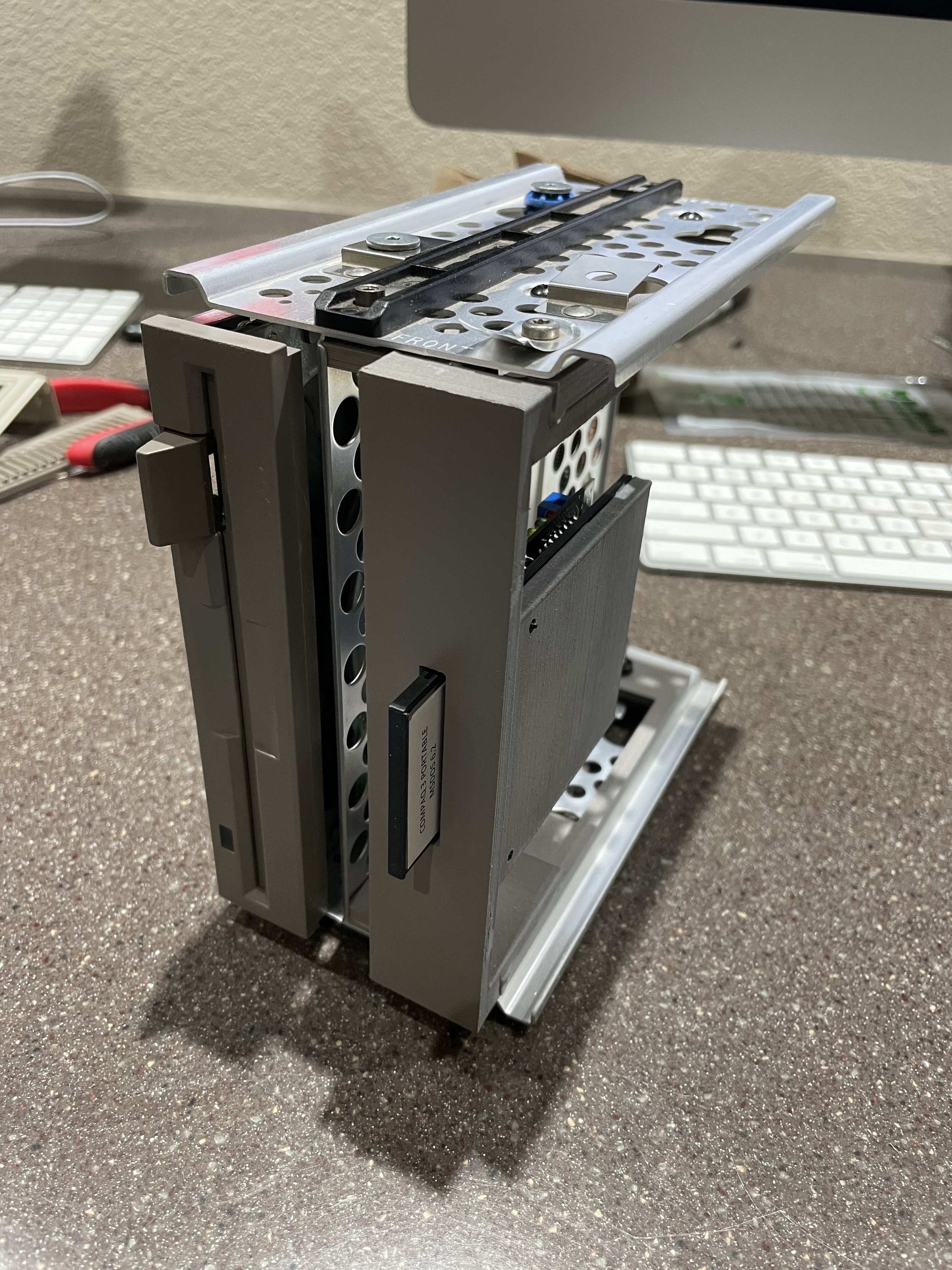
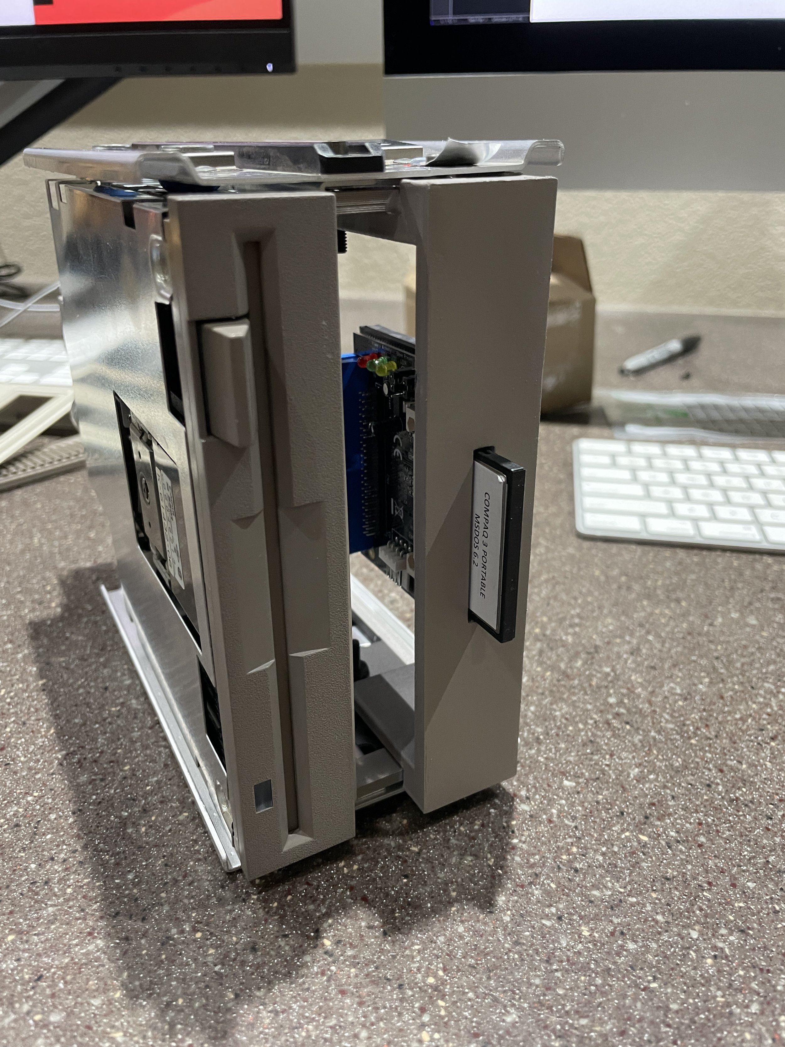
Once completed, the bracket both worked and looked great.
The Keyboard Cable Situation
As I mentioned, no CP3 keyboard cable has survived for 30 years.
The outer rubber layer is very brittle and breaks away. I knew it had to be replaced.
I wanted to match the original cable color, which is the darker color (the same as the drive bezel). I thought perhaps I could find a newer cable from a later model Compaq that I could adapt to the job.
I found one on eBay. The CP3 keyboard cable has a standard AT plug on the computer side and is soldered to the keyboard motherboard on the keyboard end.

I found that the new (old) cable wasn't quite right. It had a larger diameter wind to it than what I believed the original had. The cable needs to fit inside a tray below the screen when you close the system, and this cable did not fit well. After doing some research on the web, I found that these spiral cables are made by wrapping the cable around a steel rod and then heating them. Once cooled, the cable retains the wind. I used this method to wind the new (old) cable around a ¼ inch steel rod and heated it with a heat gun. It worked, but problems were still looming with this cable.

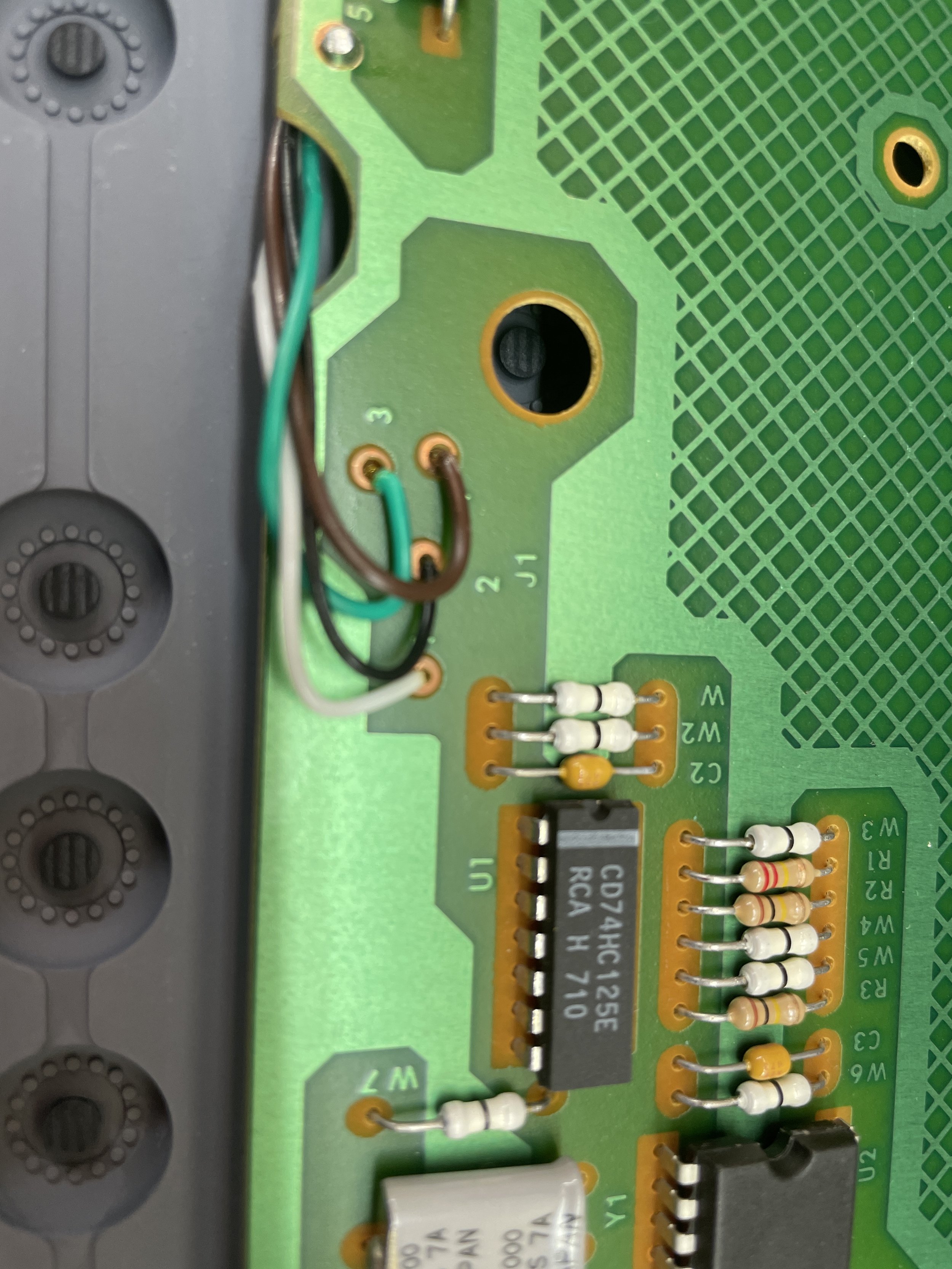
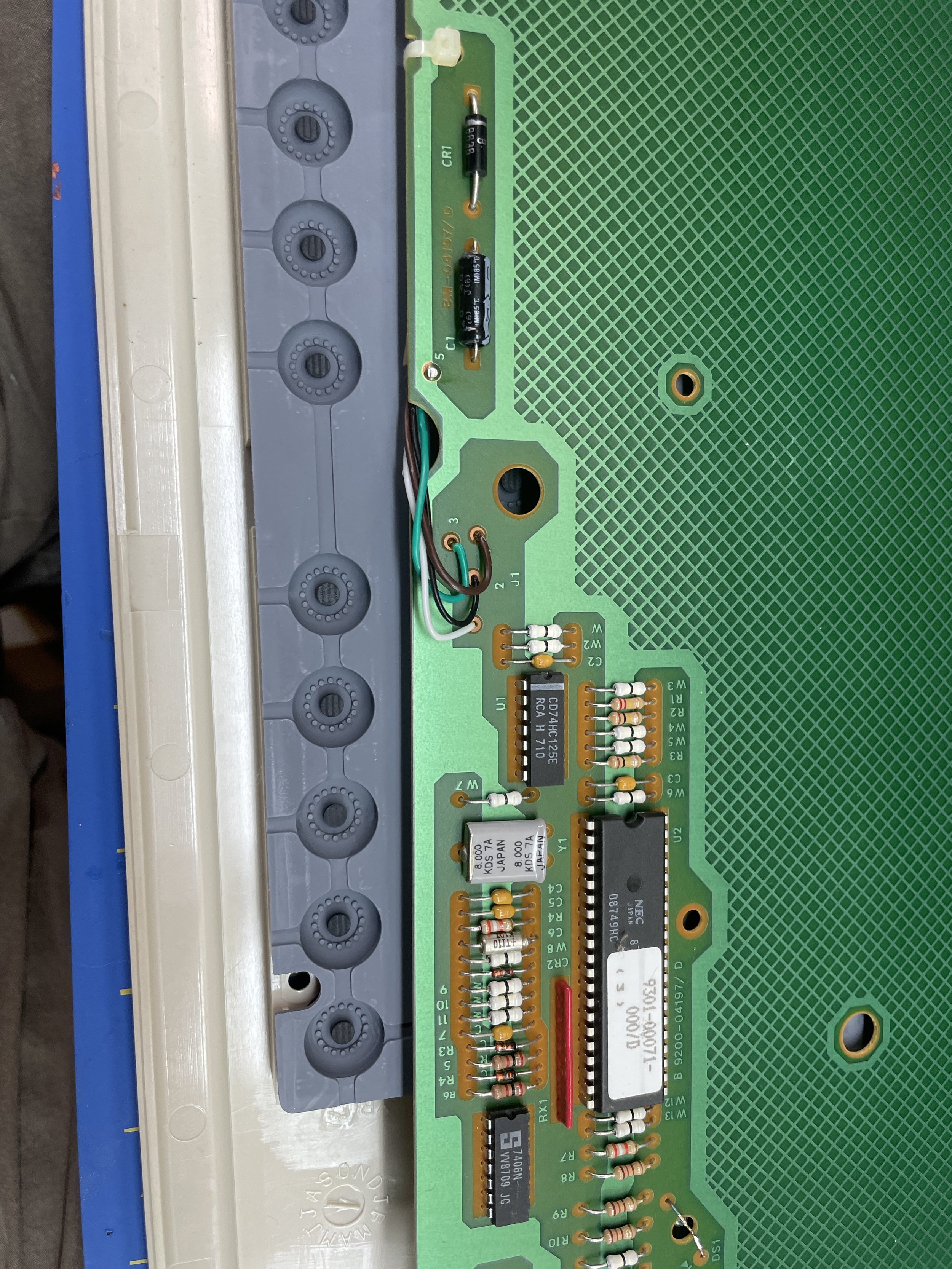
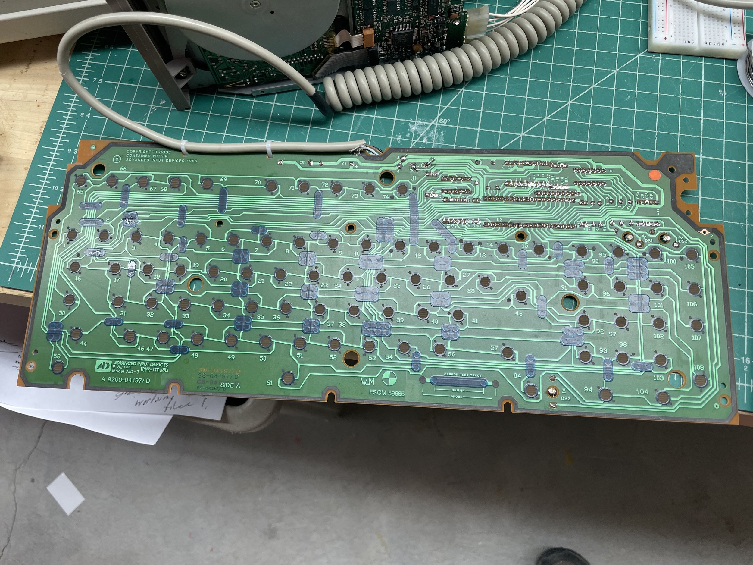
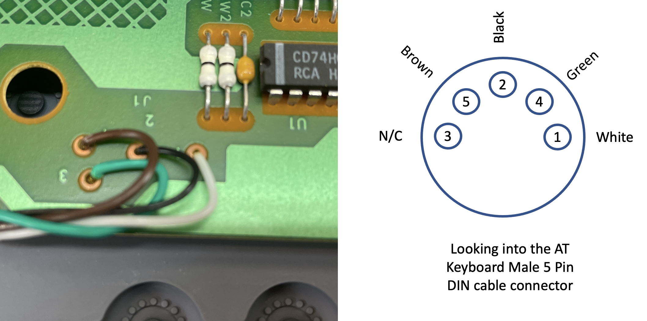
Before trying to install the new (old) cable, I took the keyboard apart and used a multimeter to ring out the signals from the AT 5 Pin Male DIN connector to the Keyboard PCB to be absolutely sure I knew what wire was connected to what pin.
It's probably a good thing I did that. The keyboard PC board has numbers next to the wire connection pads, but they did not match the standard numbering scheme for a five-pin DIN AT keyboard. I made myself a legend (posted to the right) and desoldered the original cable from the keyboard motherboard.

I have a reasonably good desoldering station and have had great luck desoldering all kinds of parts through the years. However, the traces on the keyboard PCB are very thin, and I ended up lifting the pads on two of the four wires. It took some effort to effectively solder the new wires on as I had to find traces to connect some of the wires to due to the lifted pads. Finally, after getting them all connected and, in some cases, fixed, the keyboard did work again. While this was a success, it was short-lived. The new (old) cable started to split at some of the points of stress, specifically where the cable enters the keyboard. Damn!
After a few days of living in denial that I would need to, once again, replace the keyboard cable, I ended up finding a keyboard extension cable on eBay. It wasn't the darker Compaq color, but it seemed to match the body of the computer well.
I had no idea if the diameter was correct, but it was only $5.50, so I bought it. Happily, it matched well, was new, and had the male end already installed. All I needed to do was connect it to the keyboard PCB.

I knew I couldn't desolder those wires again without even bigger problems, so I elected to solder the wires together inside the keyboard housing. My suggestion if you ever need to replace a CP3 keyboard cable is to use this technique and leave the PCB alone!
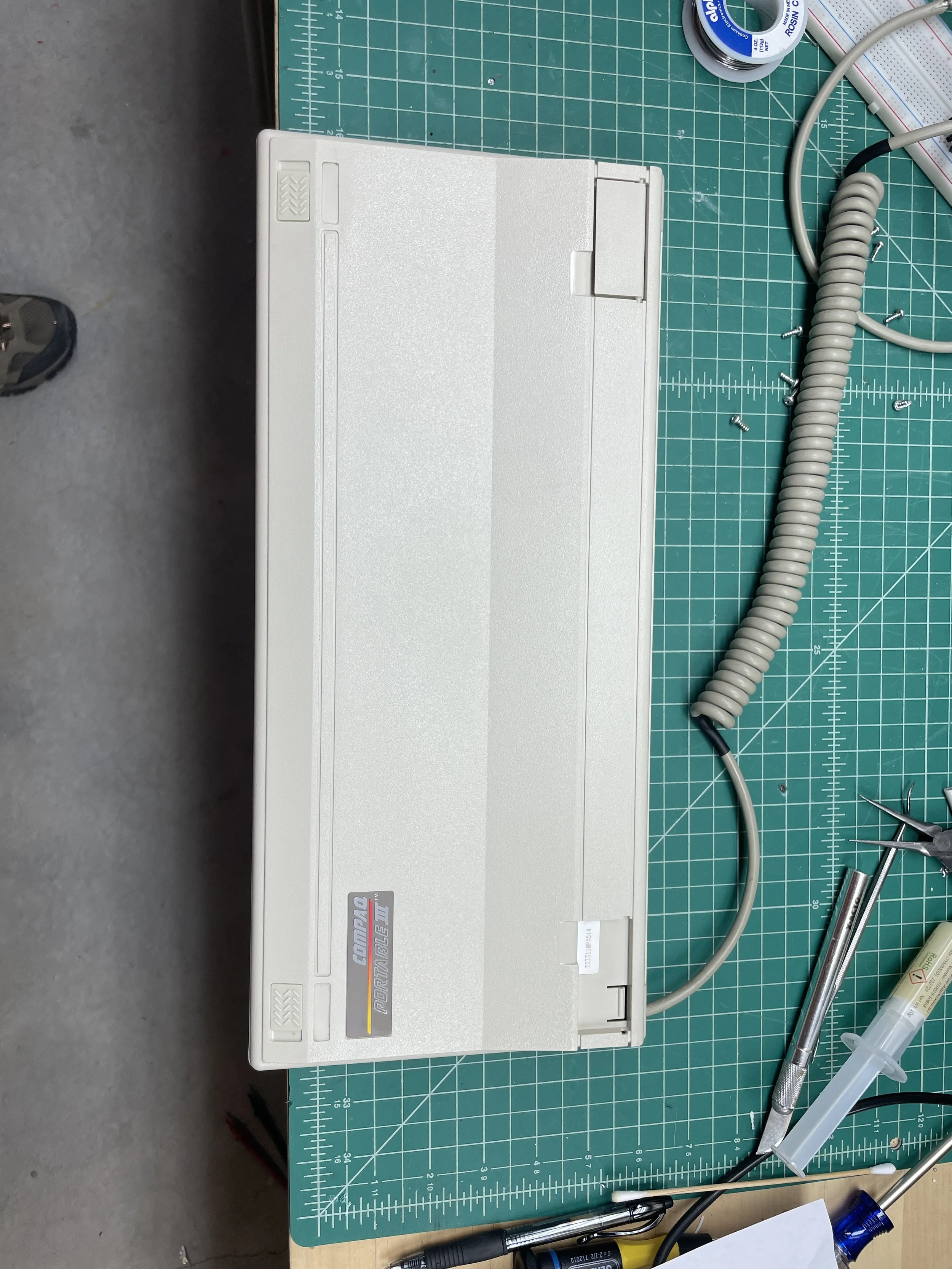
After putting the keyboard back together, the new cable worked perfectly and it looks like it could have been original.
That was a lot of work on just the keyboard, but at least is a good keyboard!

Final Thoughts
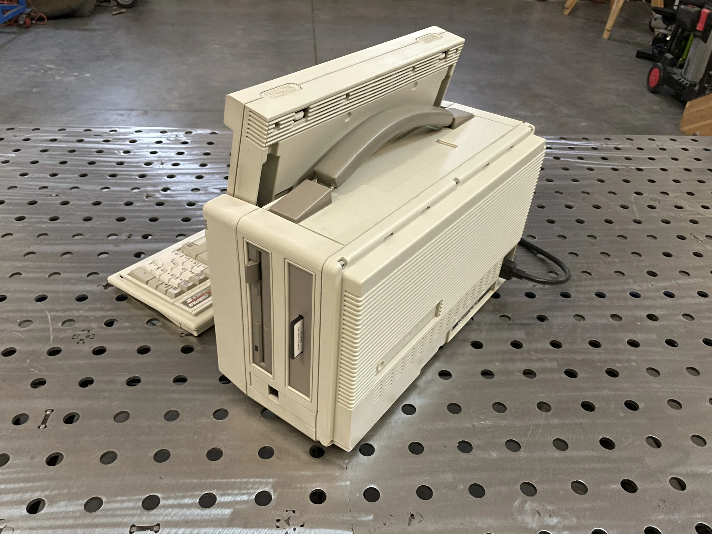
The CP3 is an unusual portable. It's much smaller and could easily be transported to work and back. It would fit under an airplane seat with room to spare and probably really fits the portable name rather than the luggable category. The screen is fascinating. It's bright and easy to read but is a bit fatiguing on the eyes after a while.
The keyboard is the star of this computer. I could easily use this keyboard every day. The keyboard has good action, a short travel, and makes all the right sounds.
Of course, nobody is going to use a 286 machine from 30 years ago, but if I had to, it would probably be this computer.
Gallery