Osborne I Portable
The Osborne 1 is the first commercially successful portable computer, released on April 3, 1981 by Osborne Computer Corporation. It weighs 24.5 lbs, cost $1,795, and runs the CP/M 2.2 operating system.

Background
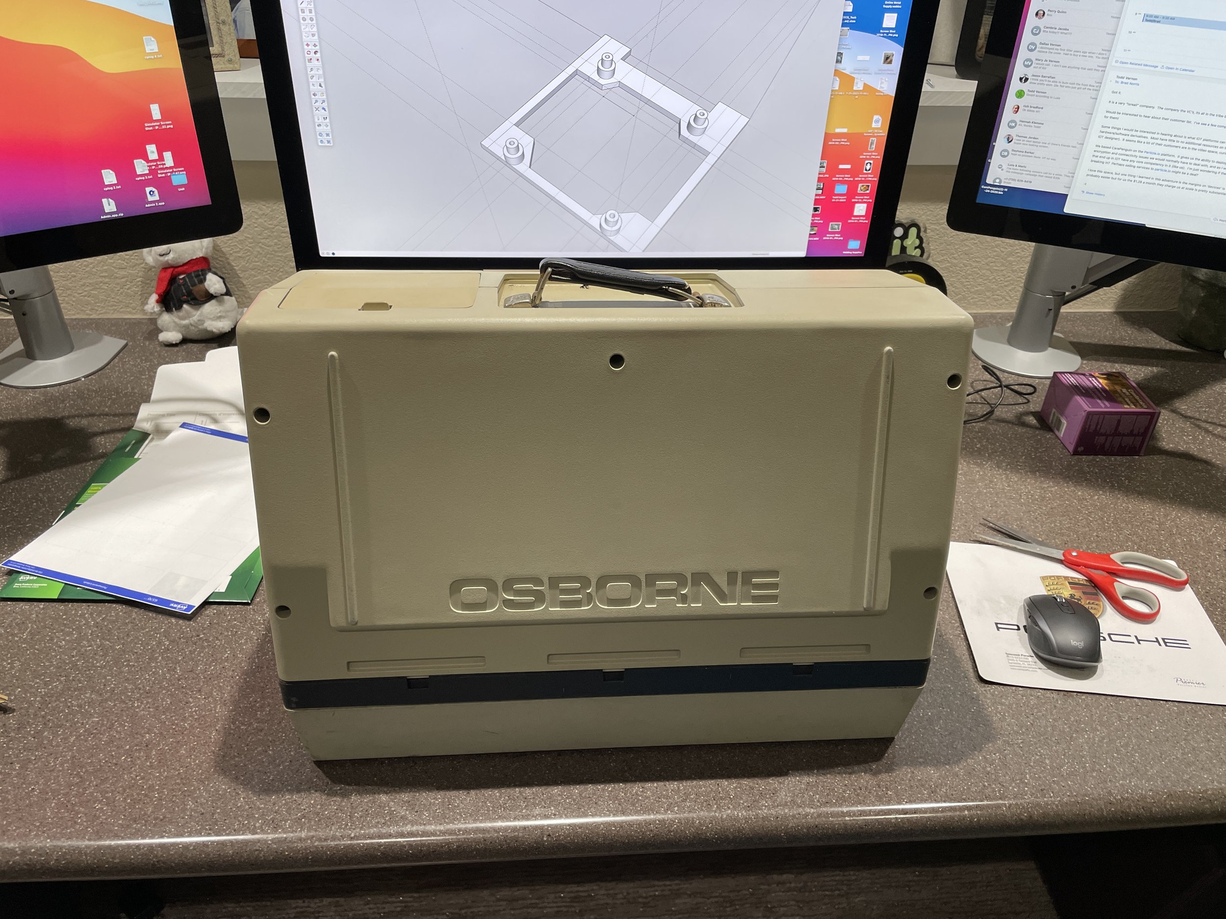
The Osborne 1 was developed by Adam Osborne and designed by Lee Felsenstein, first announced in early 1981. Osborne, an author of computer books decided that he wanted to break the price of computers. The computer's design was based largely on the Xerox NoteTaker, a prototype developed at Xerox PARC in 1976 by Alan Kay. It was designed to be portable, with a rugged ABS plastic case and a handle. The Osborne 1 is about the size and weight of a sewing machine and was advertised as the only computer that would fit underneath an airline seat. It is classified as a "luggable" computer.
This Osborne I is the oldest computer in my collection by six years, so I wanted to do it justice.
Acquisition
I bought this Osborne I from a friend, JJ Dasher, on the Vintage Computers forum in August of 2021. JJ runs Dasher Deals and I have purchased several things from him over the years. Sometimes Ebay sellers can be a little sketchy, but JJ, is a good dude. I highly recommend checking out his stuff.
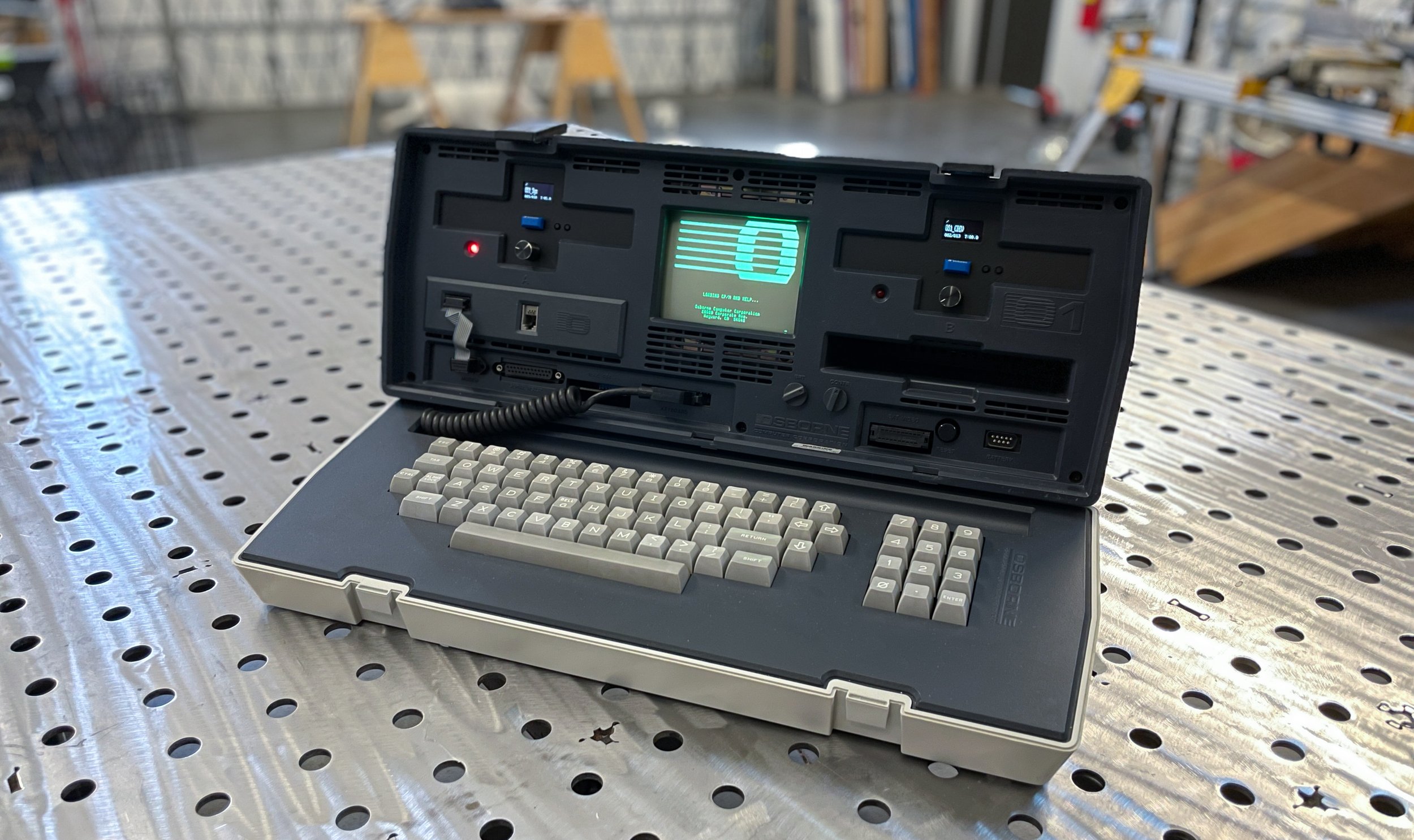
This Osborne I has a green screen. Osborne triple sourced the CRT’s in the Osborne I so you will find some with green phosphor, amber phosphor, and white phosphor. The screens were tooled for the IBM 5100 portable computer and Osborne adopted that tooling to expedite delivery of the Osborne I.
I was in the middle of the Kaypro II restoration when it came up in my group feed. It had been partially restored, so I felt more comfortable grabbing it.
Osborne I's are not that rare at this point, so that gave me some confidence that if I messed it up, I wouldn't be entirely out of luck. This would turn out to be a good thing during restoration as I did need to get a second Osborne I for parts along the way.
Condition
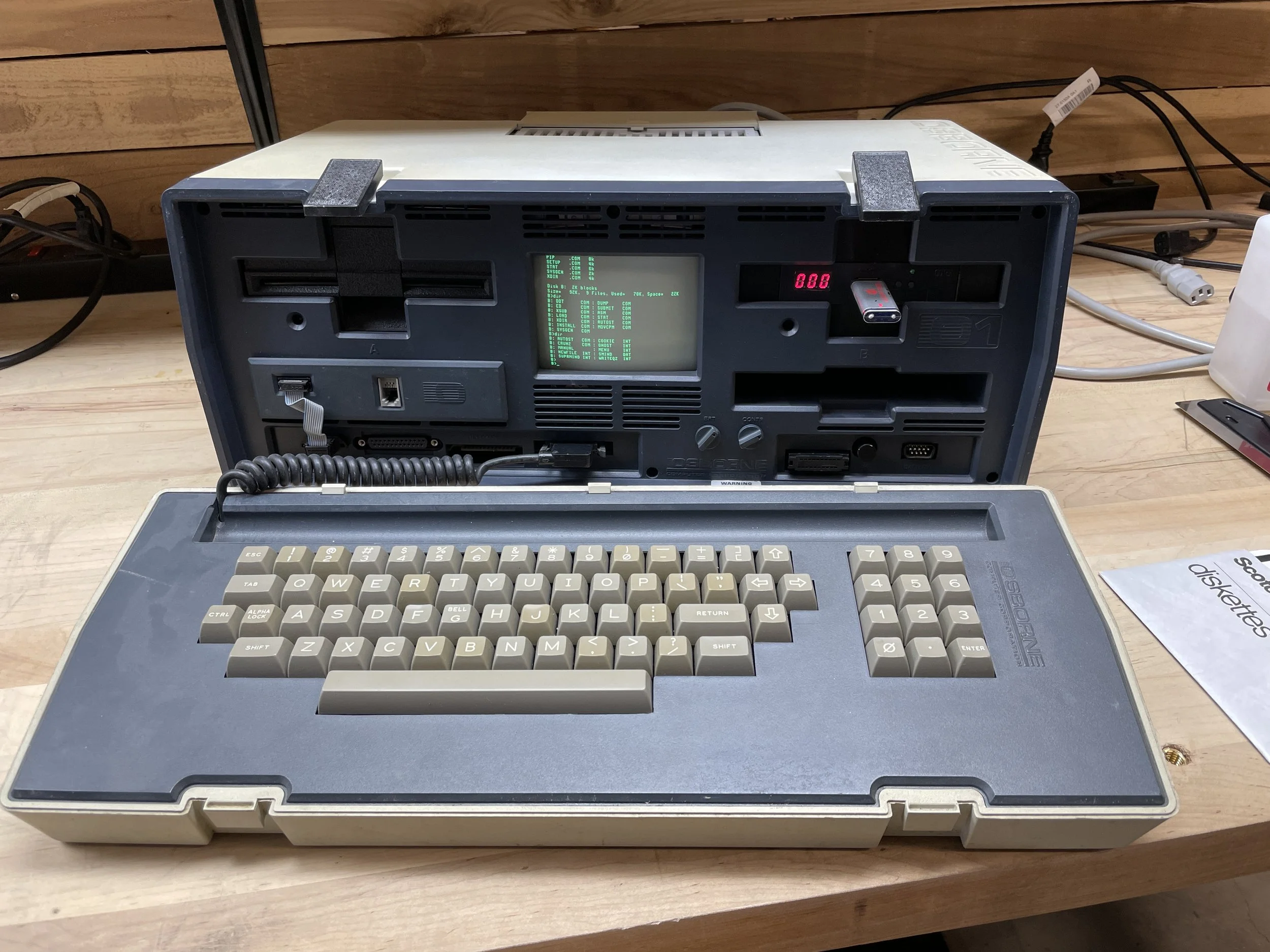
This Osborne I was in pretty good shape when I received it. It was well packed and booted right up from the B drive. Osborne computers can boot from the B drive, unlike Kaypro II's. It can, however, be a bit confusing to use the computer after booting it up from the B drive, as it logically swaps the drives. After booting it from B drive the rest of the session, A is on the right, and B is on the left. I'm sure more than a few mistakes have been made after booting from the B drive! The computer, like nearly all Osborne I's, was extremely yellowed (see the section below titled “retrobrite” for a comparison).
It was almost Fall when I got the computer, so I decided I would retrobrite the computer the following summer. This turned out to be quite a task, as I will outline below. The previous owner had installed a Gotek floppy emulator running Flash Floppy in a 3D printed carrier. The machine came with a USB stick with some common OS images and a handful of games.

Acknowledgments
When you start a restoration project, you often know nothing about the computer you are restoring. I was pretty new to the Osborne I but knew a bit about CPM from the Kaypro II restoration I had done prior.
By the time you are done restoring a computer, you literally have 20 or 30 documents and weblinks, you found along the way. I ultimately use these documents to do these documentation pages at the end of the project.
With regard to my Osborne I restoration, I would be remiss not to point out a huge source of information on the Osborne I.
Richard Loxley wrote an incredible 18-part blog post on restoring his Osborne I in 2018, and many things I did came directly from those posts or indirectly from links he referenced. I can honestly say, I’m not sure I would have finished this restore without the excellent information contained on his site.
I encourage anyone that is attempting an Osborne I restoration to read this excellent source of information.

Deconstruction
I wanted to install a newer Gotek with an OLED screen in place of the existing one, and as with most of my machines, I wanted to give the inside a good cleaning. Since I planned to retrobrite the case, I just resorted to completely taking the machine apart. The Osborne seems tough, but once you take it apart, it kind of falls into many parts. Its strength comes from being assembled.
The main components are the top case, the bottom case, the front bezel, and a pretty flimsy tray that the monitor, drives, and motherboard attach to. All the parts appear to be some sort of ABS plastic. None of the internal cables are very long, so you end up with parts on their side, and upside down, etc. Osborne I's are one of the more complicated computers to run while disassembled, and, to work on anything, it pretty much has to be completely disassembled.
After disassembly, I decided to temporarily install a spare HxC floppy emulator I had on the shelf. It initially worked fine.
Over the next few days, I moved parts around just testing a few things, and then suddenly, the HxC drive stopped working.
While debugging HxC, the real floppy stopped working. Things were going downhill fast!
Then one day, I turned on the computer, and the speaker just screamed, and the screen was full of garbage. The entire thing was just dead. Wow, I single-handedly destroyed an Osborne I.
Debugging the Broken Motherboard
After doing some research, I found out that often a bad RAM chip can cause the behavior that I was seeing. Some online forums suggested letting the computer warm up and then feeling each RAM chip with your finger. If one chip feels warmer than the others, then that is likely the bad chip. As I mentioned, doing this with the Osborne is a bit of a challenge due to the short wire lengths and layout of the system on the bench.
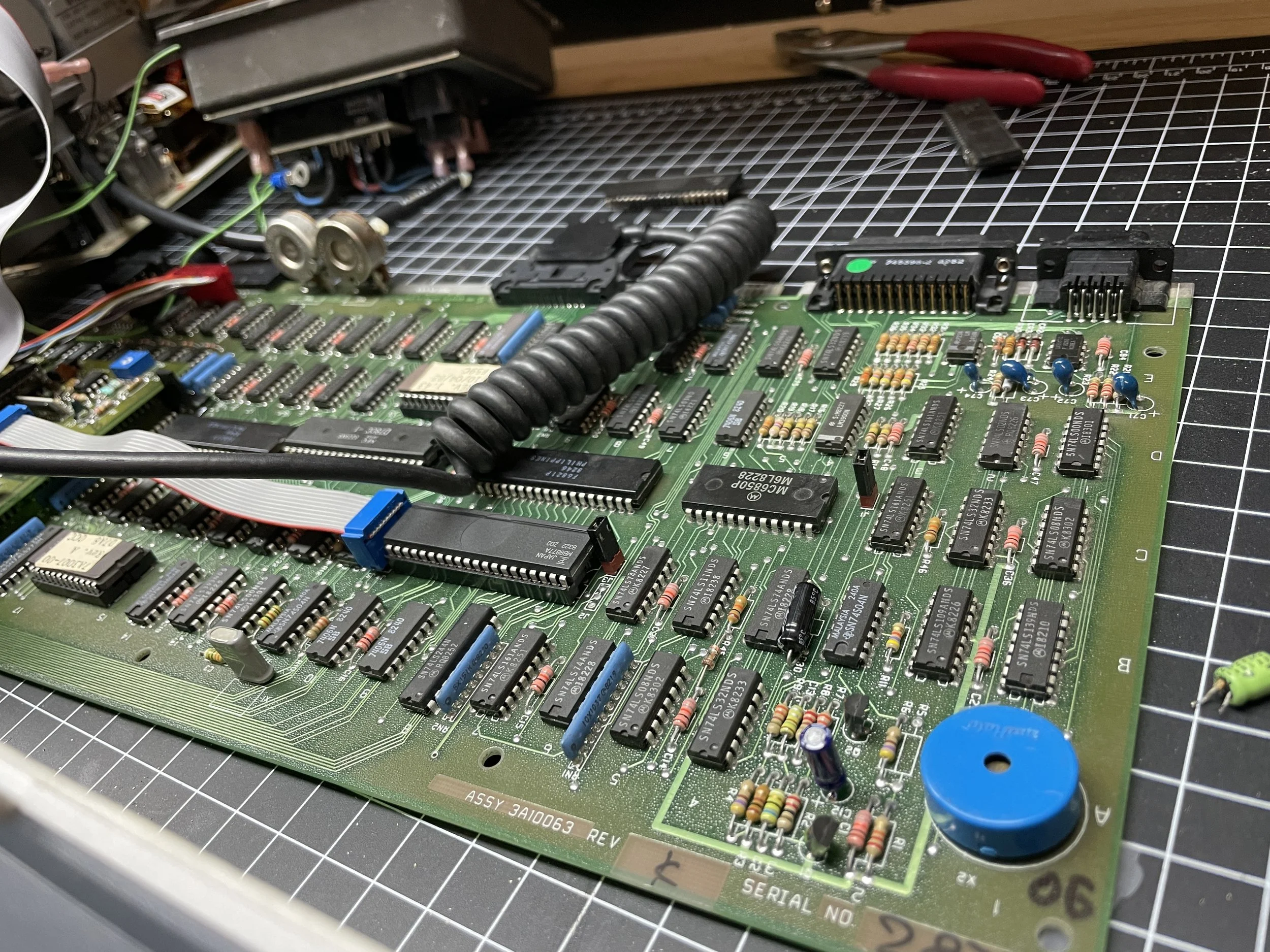
After plugging and unplugging things several times, I noticed that the system started acting normally again. After thinking about this, I noticed when plugging and unplugging things, I would always grab the board in the same location on the corner. More debugging revealed a bad electrolytic cap in the corner of the board (C12 next to the blue piezo speaker) that, when touched, would make the system stop and start working. Electrolytic capacitors are a notorious failure point on these older systems, so this didn't really come as a surprise, but the Cap looked fine.
Once I determined it was definitely that capacitor, I de-soldered it from the board, revealing that the bottom of the Cap easily broke off and the electrolyte looked brown and old. (Seen in the photo as the green Cap laying off to the side.). The Osborne I motherboard has very few caps on it, so I just ordered and replaced them all at one time, along with the double-density diskette daughter board that I had removed to test the RAM chips. While I was at it I recapped the power supply board as well, although, it looked like it had been partially done at some point in the past.

On to the Diskette Drive
I was now clawing my way back to a functional system. I realized that while debugging the drive issues, I had plugged in the HxC drive upside down, as well as the Gotek, as well as the original floppy drive.
The Osborne has one of the dumbest design features I've ever seen. The computer routes +5V and +12V over the floppy signal cable.
To make matters worse, the floppy cable card edge connectors are not keyed to prevent you from plugging the cable in upside down. If you plug the floppy ribbon cable in upside down, you end up feeding +12V to sensitive TTL +5V logic and frying at least a chip or two.
While debugging my drive issues, I accidentally cooked three different drives before I figured out what was happening. On any other system, I've restored, plugging a floppy cable in incorrectly generally just yields a non-working system with no harm done. Not on the Osborne, you clever engineers!

When I received the system, it had a homegrown adaptor between the ribbon's card edge connector and the Gotek that avoided this problem. Osborne uses the old-school card edge connectors for floppy drives, and new drive emulators use a more standard 34-pin inline connector. You generally need some sort of adaptor (or a completely custom cable) to break out the power lines on the ribbon cable to route them to a separate power connector on the emulator.
After doing some research, I found an open source board that adapts the Gotek to the Osborne 1, breaking out the +5V pins and dropping the +12V pins to avoid all this. (the purple board in the photo)
The design is on GitHub here, and there’s a link on the page to have a PC board company print you a circuit board. I bought three of them and the required connectors, and when they arrived, I assembled them.
It was a bit confusing to get an A and B drive working. The Gotek has a drive-select jumper, and so does the adaptor board. I soon realized that Gotek jumpers always needed to be configured for a B drive. Then, using the jumpers on the adaptor board, you set the drive to be either the A or B.
There is next to no documentation out there on configuring both an A and B drive on the Osborne, so this took a bit of time to hash out. I did successfully stop frying drives and did make it all work.

Bringing the real floppy back to life.
The real floppy drive was cooked from the wrong drive cable orientation, but I thought it might be easily fixed.
Using the schematics that are published in the Osborne Technical Manual, I made a diagram of what chips are erroneously connected to +12V if the drive cable was connected upside down.
It turned out to be several gates on a single IC chip U17. Those connections control things like head-seek and write-enable lines and a few other functions.
I did notice that the floppy drive head never would seek after misconnecting the cable one time, so that was a pretty good sign I might be onto something. I ordered the chip plus a few extras off the web.
While waiting for the chips to arrive, I de-soldered the U17 chip from the board on the diskette drive and installed a socket. When the chip came in, I installed one in the socket, and the floppy drive worked once again.
In the end, I left the real floppy on the shelf, as the system is much more usable with two Gotek installed, but I have it for reinstallation at some point if I wish to.

Mounting the Gotek Drive Emulators
Gotek’s don't physically fit super well in the Osborne. The Osborne front bezel covers the front of most of each floppy drive. I really didn't like the look of the installation like that. Not wanting to modify the Osborne bezel, I decided to design and 3d print a custom drive carrier for the Gotek that stacked Gotek controls vertically. On top is the OLED screen, in the middle is the USB port, and at the bottom is the rotary knob used to change disk images (i.e., floppy disks). The guts of Gotek emulators are on three different circuit boards making this configuration possible with longer jumper wires installed.

After a good bit of design work on Sketchup, I printed out all the parts and assembled them. To give the drive bezels a more finished look, I applied automotive Bondo glazing compound, sanded each bezel front smooth, and painted each with a flat black paint. To give the parts a bit more durability, I finished each bezel with a clear matt enamel finish to protect against body oils from fingers.
The Gotek has a green read/write mini-LED on the board, but I wanted to replace that with a larger red LED in the correct location for a period drive. I removed the LED on the board and replaced it with wires leading out to an LED I installed in the carrier. The hole in the carrier matches with the hole in the Osborne bezel.

You can use the existing LED leads on the Gotek (after unsoldering the existing LED), but I ended up connecting the LED to the drive-select line and an unused positive test point on the Gotek with a current limiting resistor inline.
This allowed me to select my own value for the current limiting resistor and LED, dialing in the brightness where I wanted it. I believe I used a 470-ohm resistor inline.

I think the result looks fantastic, and it’s quite usable.
When the drive is accessed, the red light comes on as it would on a real drive. I wanted sound from the drive emulator, so I connected a piezo speaker to the Gotek board. This is a nice addition as it makes a ticking sound when the virtual head changes virtual tracks. These old machines aren't very fast, so any feedback that something is working is welcome.
The rotary knob on the Gotek, used to select the specific floppy image, just clears the keyboard keys when the keyboard is attached to the unit for storage or transport.
If you want to print and assemble the parts for your own Osborne I install, they are located here.
STL File for Bottom
STL File for the USB Board Shelf
STL File for the USB Shelf Spacer
STL File for the Front Bezel
STL File for the Support Bracket
Getting Software onto the box
My system doesn't have a real floppy drive installed in it. You can, however, create and modify Osborne I disk images with various tools, including the cpmtools package on GitHub here.
This is the popular way to take individual files (like program files, etc.) and put them into disk image files that the Osborne treats as floppy diskettes via the Gotek devices.
Unfortunately, after a lot of effort, I never could successfully modify disk image files. They would always end up corrupt on the actual machine, yielding CPM Bdos Errors.
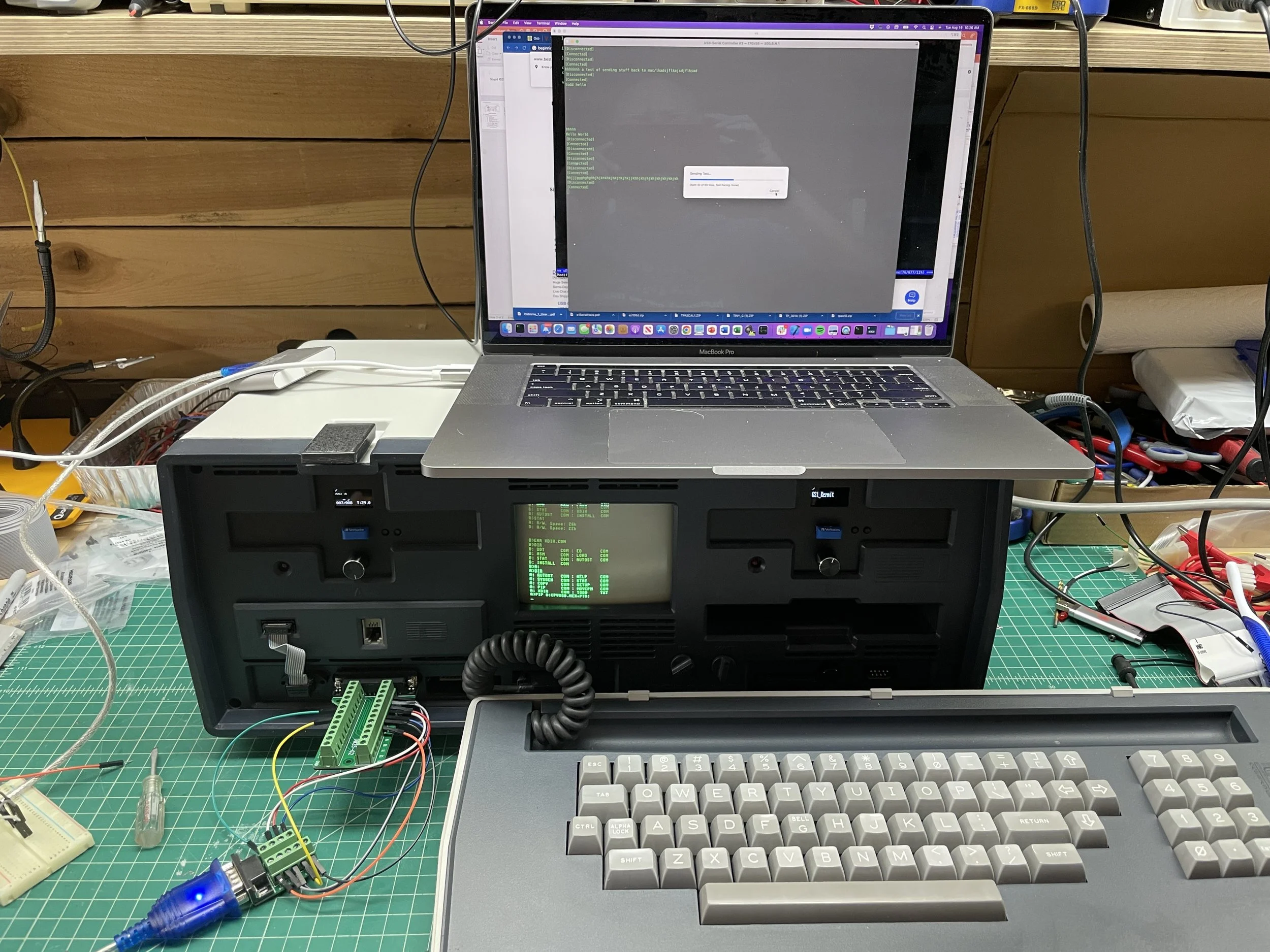
I ended up abandoning that effort and moving to directly sending files to the Osborne via a serial cable from my Mac laptop. To do this, you start with an existing disk image (i.e., floppy) on the Gotek and delete the individual files from CPM on the Osborne with the ERA command. Once you have a blank image, make several copies of that. When you want a new "floppy disk," copy the blank image to a new name, and you are ready to transfer files to it via the serial cable.

Now the trick here is you need a reliable program to transfer files over serial. That would generally be Kermit from Columbia University. Except there's a chicken and egg problem here, as you need Kermit on the Osborne to get Kermit to the Osborne.
Fortunately, I found a description of how to solve this dilemma online. CPM comes with a program called PIP (Peripheral Interchange program). It allows copying data from the serial port into a file.
PIP, while useful, is also pretty dumb. PIP reads bytes (uncorrected) into memory, and when the buffer is full, writes to buffer to diskette (or diskette emulator as in my case). However, if the transfer is larger than the memory area that PIP uses, then it writes the full buffer to the diskette, and PIP loses any incoming data while doing that, corrupting anything you send larger than the size of that memory buffer.
Reading the Toni Westbrook article online (see image), I learned you could successfully transfer an ASCII Hex dump of Kermit to the Osborne in parts, then append the parts together, load the resulting file into the debugger, and then write the full Kermit executable out to the diskette (or my case emulated diskette)
It's a lot of fiddling around, but once you have Kermit on the Osborne, then future transfers are super easy without all these arduous steps. The most challenging aspect is reassembling the ASCII hex files on the Osborne. PIP can concatenate files which is half the battle; however, the individual files always end up with blank lines in them. These must be removed before loading into the debugger as the debugger is not very smart. The only way to do that on the Osborne is using the ED.COM editor.
The CPM editor ED.COM was designed to be used on teletypes, so its use could not be more foreign and laborious. In the end, I only needed to delete three blank lines from the file I concatenated all the parts into in the combined file, but it took me several hours to get it done. After that, the rest of the process went smoothly, (although my debugger addresses were different than Toni’s) and much to my surprise, I ended up with a fully functional Kermit executable on a disk image I could use going forward.

After this, software transfer was trivial from my Mac laptop. I used the Mac program "Serial," available for free in the AppStore. Serial has a “send a file using Kermit protocol” feature that works great with Kermit running on the Osborne. Kermit can resend packets if a corrupt one arrives and handles pausing downloads while writing to the diskette.
Unlike the totally non-standard floppy drive cable on the Osborne, the serial cable is simply a straight-through cable as the Osborne I was designed to act like a terminal. A simple USB serial port from the mac (USB to 9Pin male) cable attached to a (9pin female to 25pin male) cable does the trick just fine. You do need all the control lines, so don't just try to connect the TX, RX, and GND pins; that won't work. The process Is slow (1200 baud), but then again, programs from this time were not that large.
Troubles with Turbo
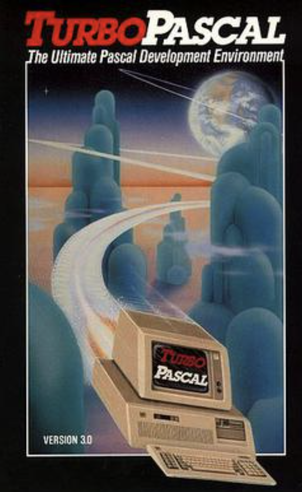
I was a programmer for a lot of my career, and my first real language was Pascal, specifically Turbo Pascal 2.0, then 3.0, before moving on to C, C++, etc.
Turbo Pascal runs great on CPM machines and old DOS machines and is widely recognized as the first Developer IDE (Integrated Development Environment). It has an integrated editor and single pass compiler that compiles straight to memory, making it easy to build apps fast on machines that are not fast. I run Turbo on my Kaypro II as well as all my DOS boxes. While it takes a bit of time to get back into the Pascal mindset, Turbo is quite nice for building small software utilities quickly. In addition, there is a lot of Turbo Pascal source code out there for various programs people wrote back in the day.
Turbo Pascal 2 and 3 also run on CPM machines, including the Osborne. In all environments, DOS or CPM, you first run TINST.COM to install the program. The name is a bit misleading as it really doesn't install the program but rather modifies some configuration information, so the program understands the hardware on the specific computer. Running Turbo Pascal on CPM, getting the TINST.COM configuration correct is important as most CPM systems were built to double as terminals. The problem is that they all emulated different terminals. TINST.COM configures the terminal escape sequences much like Termcap does on Unix or Linux computers. When you run TINST.COM you select the terminal type, and there is a selection for Osborne I. Unfortunately, the terminal definition appears to not be correct, or something else is wrong because I was never able to successfully configure Turbo for CPM on an Osborne I. The main IDE screen appears to work fine, but when the program drops into editor mode, the screen is garbage, and the machine freezes up. I had no problems configuring Turbo for the Kaypro II, so I was surprised it just didn’t work on the Osborne. I tried all this with two different versions of Turbo Pascal (2 and 3) and got different but equally nonfunctional results. If you know something about how to do this successfully, please contact me with the link on the site and correct the error of my ways.

Retrobrite
The Osborne I was a tough restore. When I got the machine, like all Osbornes of that era, the plastic case was bright yellow from UV light damage. The keycaps were green, and the plastic was yellow. It just looked horrible. Not bad, horrible.
I knew from the beginning I was going to retrobrite the entire case, keyboard, keys, everything. I also knew from experience that these old machines are very difficult to retrobrite successfully. The only way I have been successful with older machines is to completely submerse the parts in hydrogen peroxide + water + sunlight; otherwise, the plastic streaks, and you can basically ruin the box.
The Osborne comes apart into many parts, but you still need a reasonably large container to retrobrite the individual components. I also went through probably $30 of hydrogen peroxide in the process as there are a lot of parts, and most needed at least two days in the sun to get back to normal.

Despite my forethought and care, I initially made a serious mistake. With a lot of my restored machines, I have started this process by running individual plastic parts through the dishwasher on the fast cycle. I do this with circuit boards all the time, and it works great. I've done it with more modern plastic cases, and keyboard sections with no problem. When I did this with the Osborne I upper section and keyboard housing, they literally melted.
This was a really bad situation. I realized there was no recovery from this, so I started looking for a second broken Osborne I that was for sale but with a good case. I soon found one with a good plastic case and did not repeat that mistake. In the end, I used the power supply from the second box after recapping it, and I have various spares for the future (some parts working, some not).
After two days of retrobrite efforts, all the parts came out looking quite good. It's a little tricky to get them all about the same color and close to the original color, but It's doable with patience.

Final Thoughts
The Osborne kind of grows on you as you play with it. Its tiny 5" screen is readable, at least at its 52-character width. While 40-character screens always felt too limiting to me, 52 works for a lot of programs just fine.
From what I understand from reading various forums, it was pretty typical for users to have an external monitor where they could use a larger screen when at home or in the office. Osborne sold a ScreenPac upgrade that let you select more standard screen sizes, but to me, that feels like that was probably incompatibilities on top of incompatibilities. In comparison, the Kaypro II, which followed the Osborne I, was a much nicer experience (although larger and heavier) but had a 9" 80x24 characters screen.
Hands down, If I had to make a choice, I would select the Kaypro II. Nonetheless, there is something charming about the Osborne I, and once you got used to its quirks, I'm sure the original owners were quite happy with the machine.