NCR PC4
The NCR PC4 was introduced by NCR Corporation in 1985. It was one of the early entries into the burgeoning personal computer market and was designed to compete with established players such as IBM and Compaq. The PC4 was marketed primarily to business users, focusing on its reliability and design. I believe it was used a lot in the banking industry.
The PC4 featured an Intel 8088 microprocessor and 5 ISA expansion slots. It came in many configurations, including a two-floppy drive configuration, one floppy drive, and one hard disk configuration. The PC4 supports up to 640Kb of RAM, with 256K on the motherboard. Its compatibility was not perfect, and later NCR released the PC4/i that improved on some of the compatibility issues. Some say the “/i” referred to “really IBM compatible.” In addition to its technical specifications, the PC4 was notable for its all-in-one design. The computer and monitor were integrated into a single unit, which saved space and made it easier to set up and move around. This differed from earlier PC designs, often requiring a separate monitor and bulky system unit.
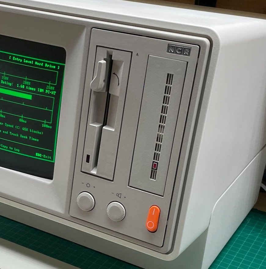
The standout element of this computer was its industrial design. The year it was released, NCR won the German International Forum Design award for the PC4 industrial design. To be honest, I bought it simply because it looked cool, and I remember it in the computer store the year I graduated from college.
While the PC4 never achieved the same level of commercial success as some of its competitors, it remains an interesting and important footnote in the history of personal computing.

Acquisition
I found this PC4 on eBay in January of 2023, I paid around $299 plus shipping. I’ve always liked the design of this computer. It just looks like a computer from the future, even today!
This PC4 was particularly attractive to me because its case was nearly flawless. A few parts were a bit yellow, like the floppy drive bezel and the bottom of the keyboard, but not nearly as bad as some units. While most computers of the era were metal or plastic, the case of the PC4 appears to be molded from hard resin and then painted. The case is quite thick, it’s very strong, It's HEAVY, and the painted finish is tough. I was confident it could cosmetically get back to 100%.
Computers like this can be a little tricky to buy and restore. The industrial design of the machine is so important you have to have all the original parts to really pull off the restoration. The working floppy drive was key as were the controls on the front. The keyboard was in perfect condition as well.
On the downside, the machine was listed for parts or repair. The listing said it would not power on. I don’t generally buy machines in a completely unknown condition, especially with an integrated CRT. But, I made an exception for this computer, hoping its problem would be obvious once I took it apart. Early 8088 computers use few custom chips so you can generally find any part you need.
When I received the computer, it was packed in a cardboard box with two additional layers of cardboard but little other packing material around it. Despite that, it looked fine when I unpacked it, and it suffered no ill consequences of its travel, although my back suffered carrying it downstairs into the lab!
To say this computer is heavy is an understatement. The PC4 is between 50 and 60 lbs. Due to its form factor and the offset mass of the CRT, it’s a bear to handle. In other words, this is not an easy computer to move around, although apparently, that was a selling point of the all-in-one design.
Disassembly and First Looks
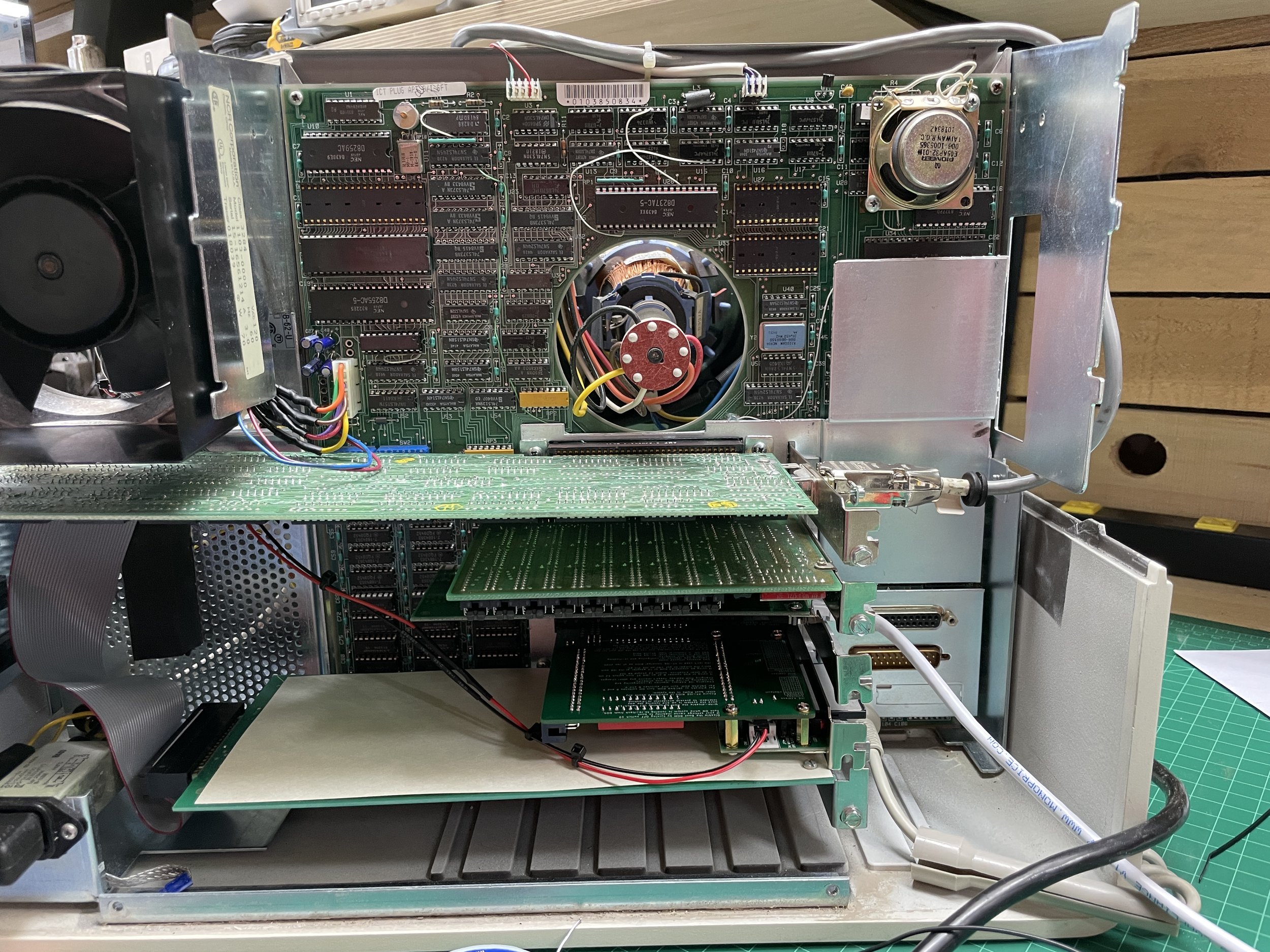
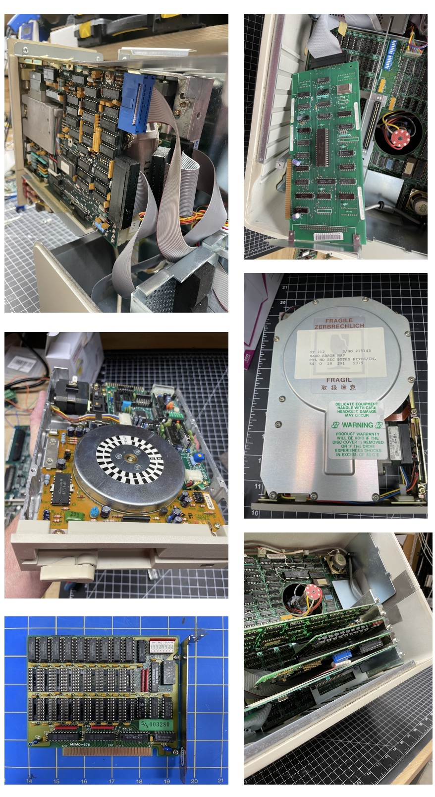
I was anxious to disassemble the chassis to see what I bought. Two things strike you immediately when you disassemble this computer. First, NCR was bound and determined to achieve this industrial design. The motherboard has a hole in the middle for the yoke of the CRT, and the ISA cards are embedded inside the computer. It’s a very unusual design. The second is how many bodge wires there are on the motherboard and some of the cards. NCR clearly did not feel the need to get these boards perfect before shipping the system.
I suspect NCR was a little under the gun to get a machine into the market, and the margins on computers at that point allowed for a little manual work. Also of interest is the sheer number of different screw types, heads, etc. Other manufacturers of the time were already trying to use the same hardware as much as possible. At one point I probably had 20 labeled envelopes with screws and parts I knew I would forget unless I labeled them.
When disassembling the PC4, I was first looking for a smoking gun regarding why the machine was not working.
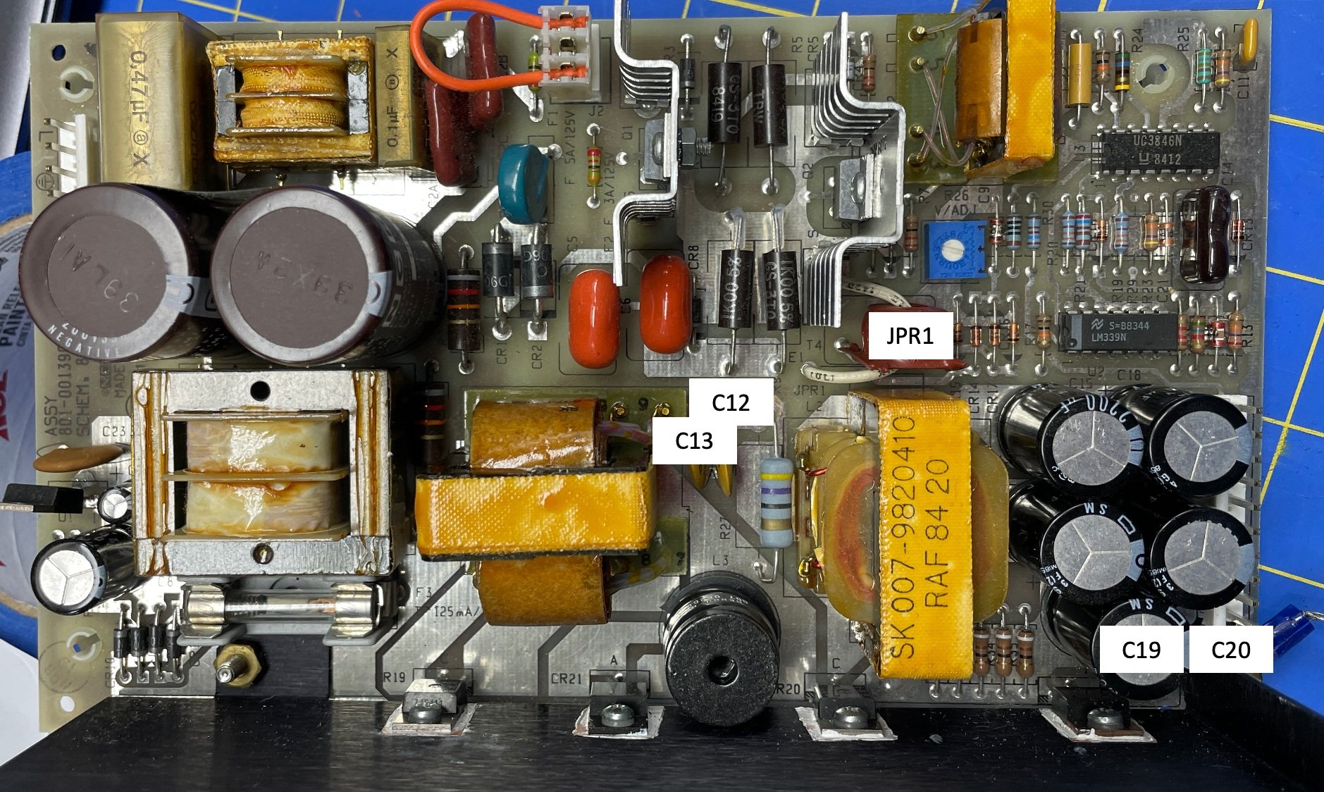
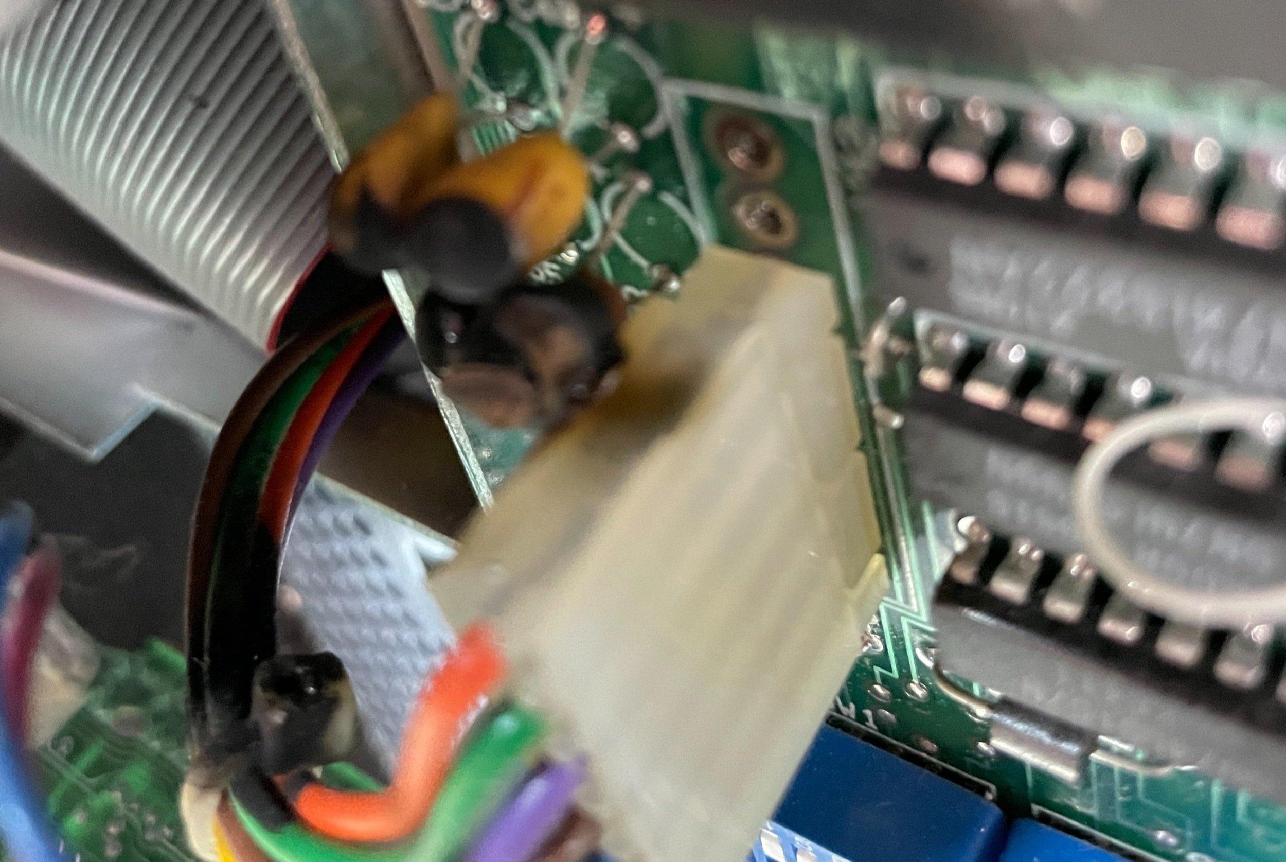
I was not disappointed as I immediately found an electrolytic capacitor that had exploded on the motherboard. It had burned three other capacitors near it and melted part of the connector from the power supply board. Black smoke had coated other parts of the inside of the case as well. This was humourous because the seller on eBay stated, “Nothing is burned on the inside.” That seems odd statement to put in the description, especially when something is obviously burned on the inside, LOL.
In any case, I saw this as pretty good news and likely the cause, or perhaps a symptom, of the problem. It's always nice to have a place to start when repairing a broken machine. I continued disassembling the machine until I got to the power supply unit. The power supply appeared to be in good condition.
The Parts
My PC4 was configured with a 720 x 348 monochrome graphics card with Hercules Graphics emulation that appeared original to the machine.
It has a Teac 55B-62-U 360K Floppy Drive in perfect working condition that appeared original to the machine. This model of floppy drive is very reliable in my experience.
The floppy controller and Winchester Hard Drive controller boards appear to be original as they have similar QA notes on the top of them that match the style on the motherboard and both appear in the Hardware Reference Manual.
The Memo-576 RAM expansion card was partially populated with 384K of memory chips. This card was certainly an addition made by a previous owner, a system integrator, or a retail store. The Hardware reference shows an additional RAM card, but this is not that card.

Obtaining the Schematics
I bought this machine without knowing if the schematics were available. That’s not a good idea with machines like this. Computers from this era had excellent Hardware Reference Manuals that were hundreds of pages long, including full schematics of the motherboard, power supply, analog video board, and all the original peripheral cards.
I believe the PC4 was NCRs first attempt at a PC compatible. The second attempt was the PC4/i which reportedly has better compatibility. I quickly found the PC4/i Hardware Reference with schematics, but it was obvious by looking at them that these two machines had very different motherboards and physical configurations inside the machine.
After a few days of digging on the internet, I found the correct Manual with schematics, and it was a good thing as I would spend a lot of time with them restoring this computer!
Link to the NCR PC4 Hardware Maintenance and Service Manual (Part 1)
Link to the NCR PC4 Hardware Maintenance and Service Manual (Part 2)

Source of the Capacitor Explosion
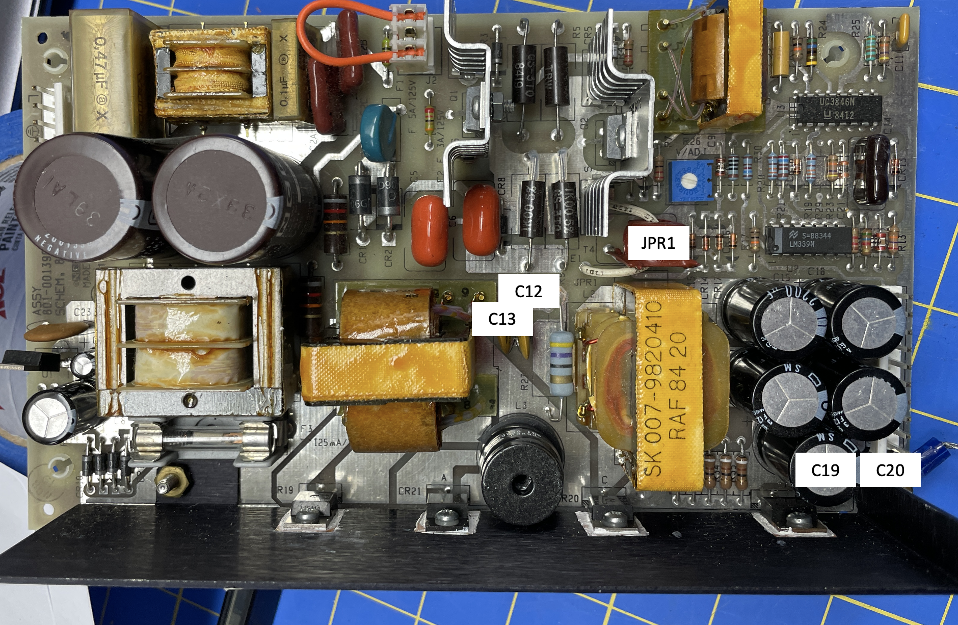
Using the schematics as a guide, I determined that the exploded capacitor on the motherboard was a filter capacitor for the +5V input from the power supply.
I’ve found that the schematics often don’t match the board perfectly. In this case, the schematics show two different capacitors in parallel to ground for most of the inputs. The .1uF capacitors on the schematic did not exist but the 33uF capacitors did.
I then tested the power supply on the bench and found that none of the outputs (+5, -5, +12, and -12) were working. The fuse on the input of the machine and the several fuses on power supply itself, all appeared to be in good condition.
After removing the damaged capacitor and its adjacent friends from the motherboard and the five others from the power supply, I ordered replacements from Digikey.
Capacitors are cheap, and it wouldn’t hurt to do a bit of a shotgun approach to changing them out.
In addition, I replaced the two AC line level RIFA X2 Capacitors as they are routine failure points for power supply of this age.

Debugging the Power Supply
After recapping the power supply, I tested it again and was pleased to see that the +5V supply was now functioning.
However, the other outputs still weren't working. After thinking about this a little more and consulting the schematics again, I noticed the presence of a current sensing circuit.
I realized that the other power supply rails might not be enabled unless power is drawn from the +5V supply line. I had seen this with other computers and power supplies.
Not sure what else to do, I decided to put the system back together and try it.
The machine booted up successfully from the floppy drive! I checked all the supply rails, and they were all functioning correctly. Win!
Although I'm unsure of what caused the +5V capacitor on the logic board to fail, I suspect it either shorted due to age or someone accidentally connected the power supply to the motherboard cable backward. The connector is not keyed that well, and I could see how someone not paying that close of attention might get the connector on there backward or offset a pin or two.
Despite not knowing the exact cause of the issue, I feel confident that recapping all the other voltage rails was a good idea. After removal, I noticed that one of the old capacitors was leaking a bit.
Now we are getting somewhere!
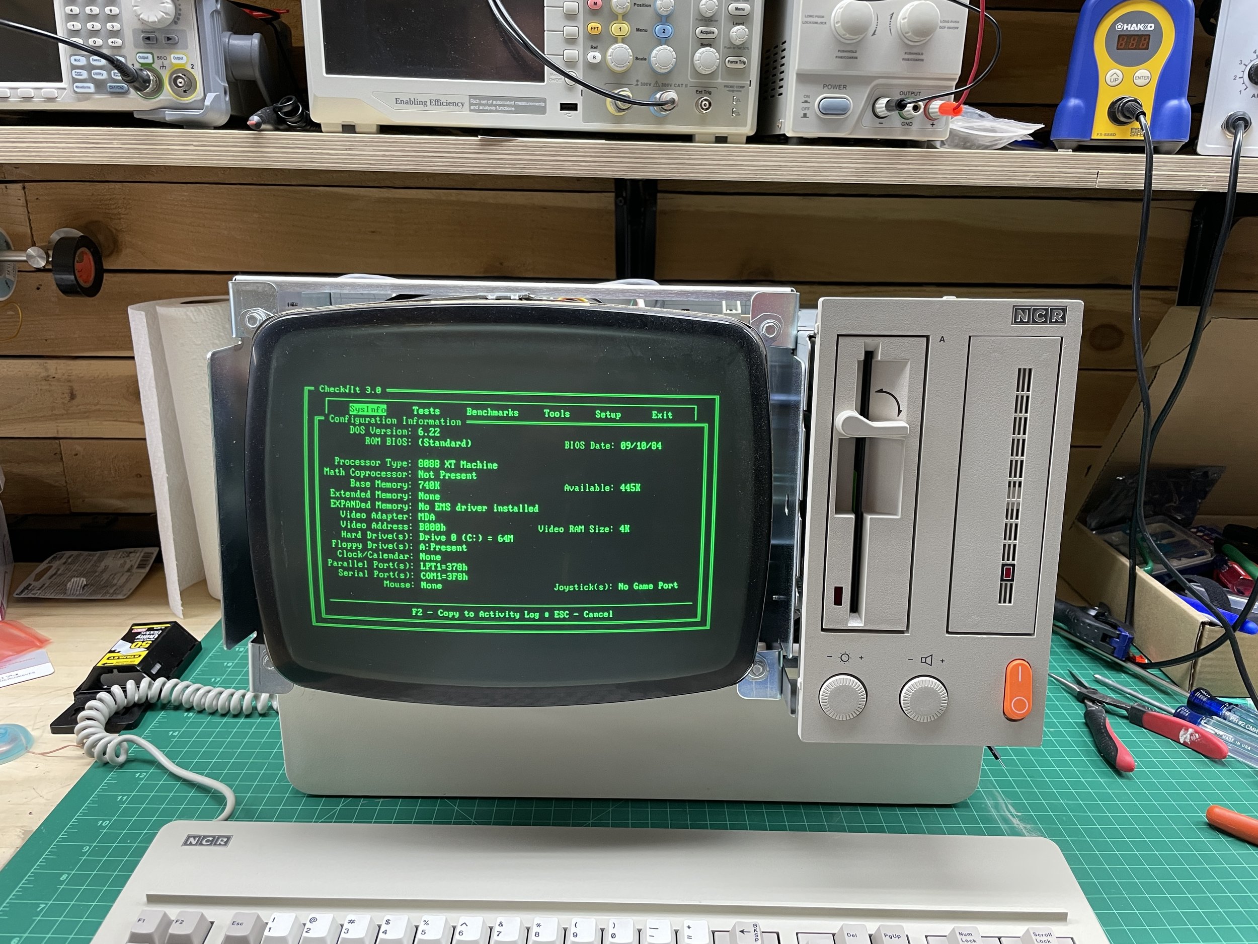
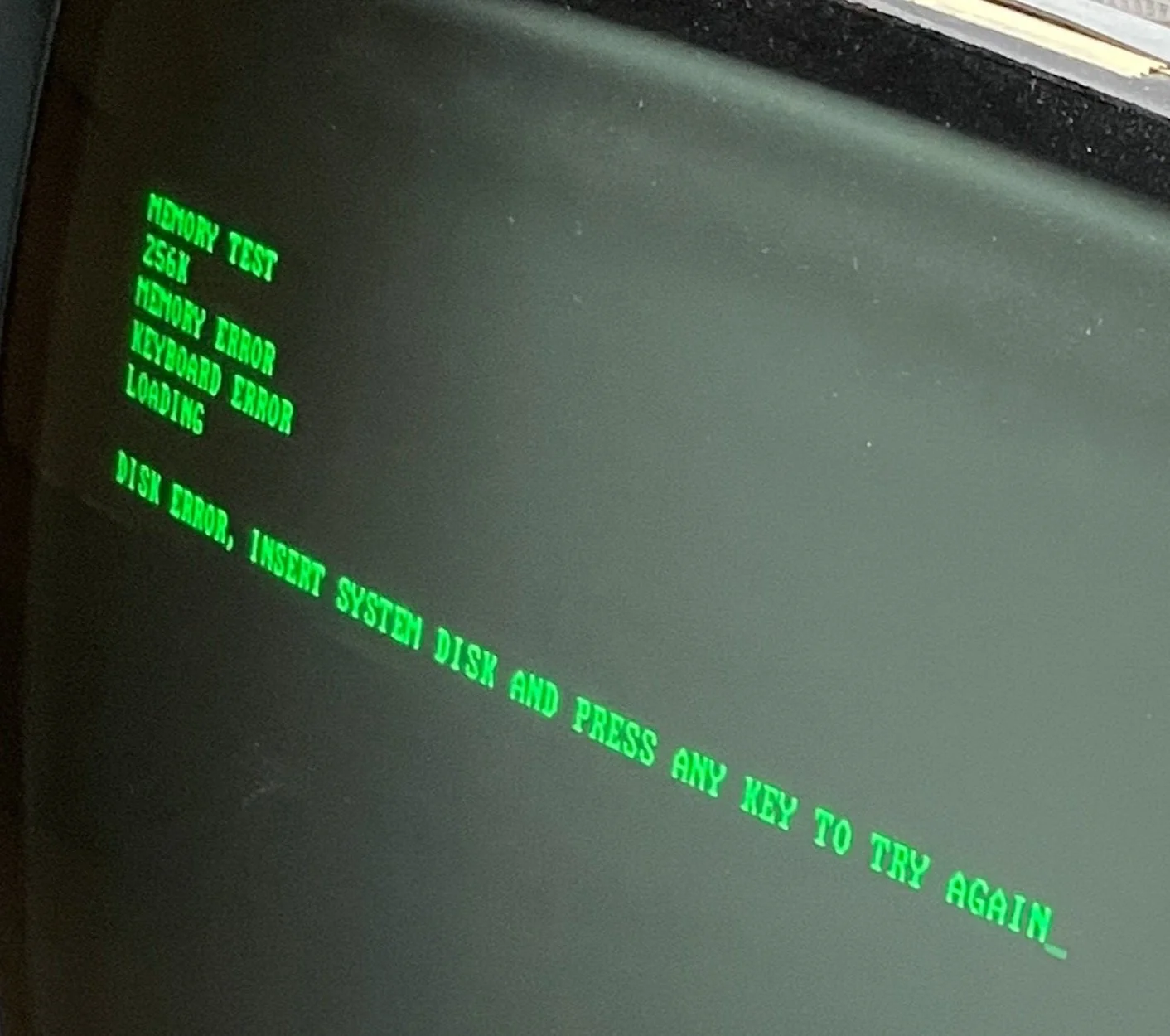
I finally got to see the screen! At this point, I had had the computer for weeks and had yet to know if the screen actually worked. I thought it probably did because I could see the tube heater was powering on, but you never know.
During the power supply testing - in system, I encountered several BIOS errors on the screen while booting but assumed those to be related to all the missing cards that I had removed from the system during test.
Once I returned all the cards individually, I was left only with a Keyboard error.
I disassembled and inspected the keyboard, but everything appeared to be in good condition. At this point, I thought a key was stuck in a depressed state, causing the error. I don’t know, just guessing at this point!
Since I had the keyboard disassembled, I went ahead and cleaned all the keycaps and keyboard PC boards. Surprisingly, the keyboard was in excellent condition and even featured Cherry switches, renowned for their high quality. The PC4 was the first machine I encountered with Cherry key switches from that era.

Keyboard Issues
I started with the keyboard itself to troubleshoot the keyboard issue, suspecting a stuck key switch. I connected the keyboard to a bench power supply and connected the data and clock lines to my oscilloscope. I was fairly sure the keyboard was working because pressing the caps lock would light the LED, and pressing it again would unlight the LED. This generally means the keyboard controller IC works on older machines. In later machines, the computer controlled the state of these lights, but the XT Keyboard design only uses unidirectional communications from the keyboard to the CPU.
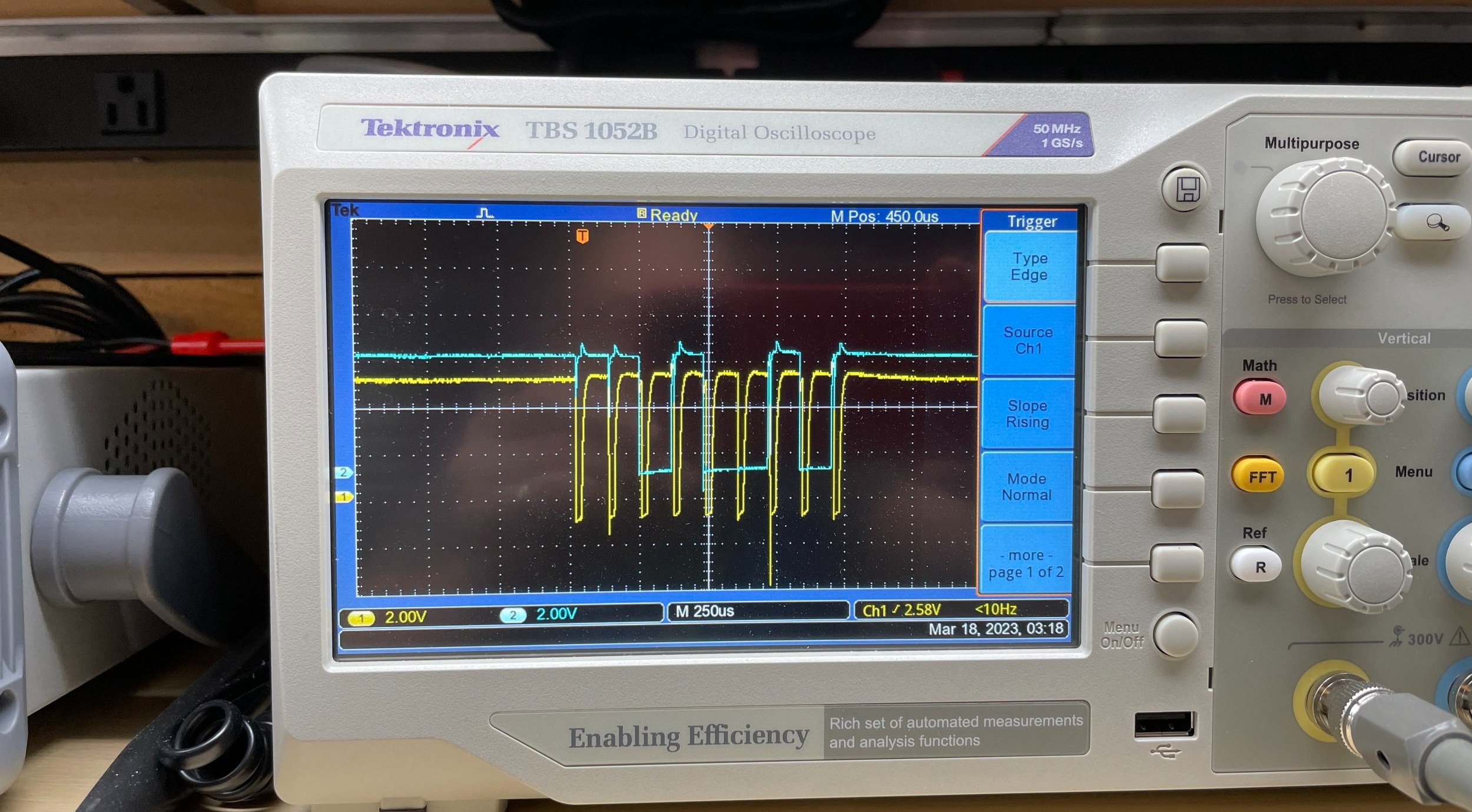
Typing on the keyboard showed that the clock signal (yellow) was working fine, and the data lines (blue) were switching between states as one would expect
Every key had a different blue bit pattern also what you would expect to see. Key presses and Key releases send different codes. The difference between a key press and a key release is only the first bit (ie sign bit), making it pretty easy to see on the scope that the data was valid.
However, the keyboard did not announce itself when powered on. I was pretty sure it should, but I never confirmed that.
Happy that it was transmitting what looked to be correct data and clock, I just decided to press forward.

I then turned to the motherboard schematics.
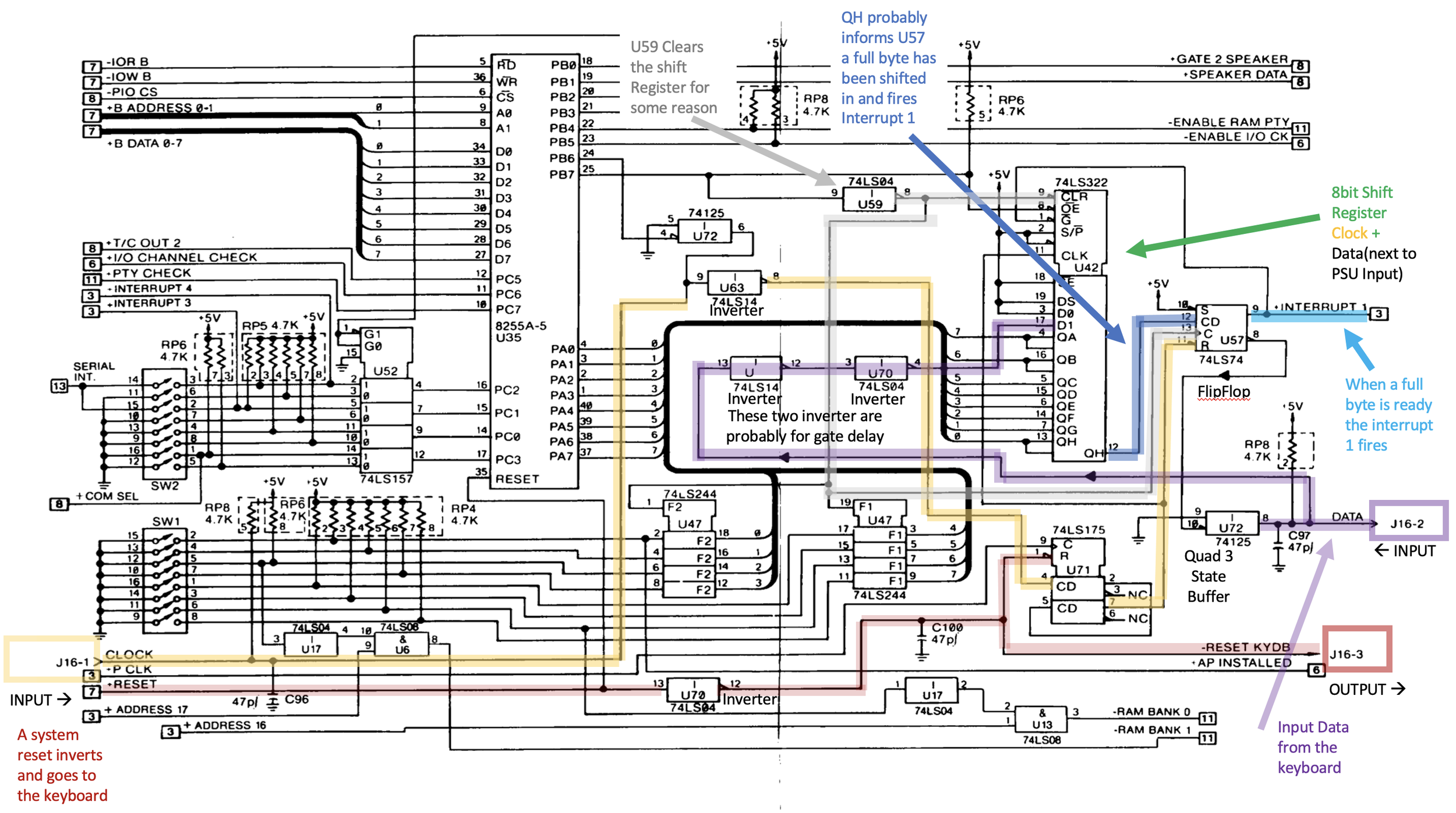
My plan of attack was first to see if Interrupt 1 was firing. From what I gather, Interrupt 1 is fired when a complete keycode is received serially from the keyboard. This interrupt tells the CPU that a keycode has been received and is ready to read.
I looked at the schematic and highlighted the clock and data signals that passed through the system. The Clock is the yellow line to the left, and data is the purple line coming in from the right side of the diagram.
Starting at the serial-load parallel-out shift register that fires the interrupt (Cyan line on the right), it was, in fact not ever triggering. Working backward, I could see the clock and data being presented to the chip, but nothing came out. I had a similar debug session on my Kaypro II, but it was one of the earlier buffer chips in the data path that was broken. On the PC4 the signal reached the 74LS322 shift register, then died.
Lending some credence to this, the Hardware Reference Manual suggested this chip might be the problem, AND this chip was located adjacent to the capacitor that had exploded.
I ordered a new 74LS322 and replaced it after removing the original chip and installing a socket.
Interestingly, the faulty IC was located next to the exploded capacitor, lending some credence that this was indeed the problem.
After the new IC was installed, the keyboard started working again.
However, this would not be the last keyboard mystery I would encounter.
It Works! Almost!
After putting most of the parts back together in the chassis, I again encountered keyboard errors.
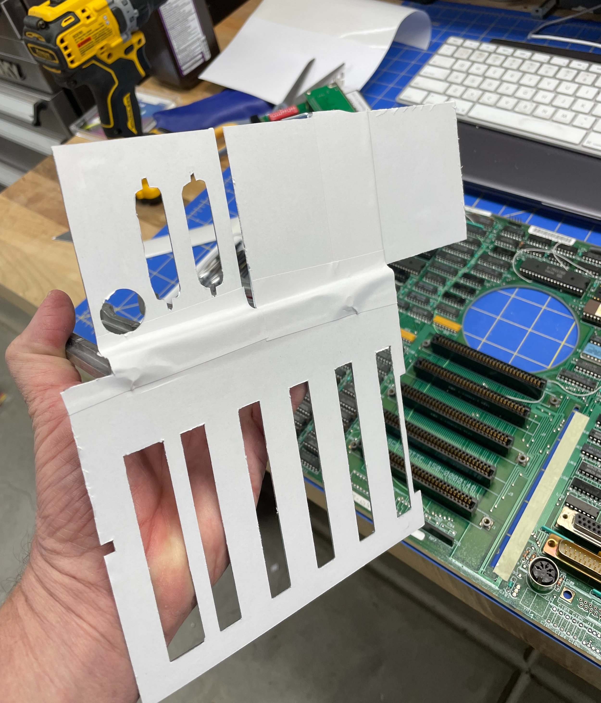
I had a hunch that the metal cross braces that connect to the chassis and support the ISA cards were possibly touching something on the motherboard, causing issues.
I had already ruled out actual keyboard issues during my previous debugging with the machine taken apart, and it was now working consistently disassembled.
To test my theory, I applied adhesive paper to the metal parts' inside (motherboard-facing) side and reinstalled them. This solution worked perfectly, and I encountered no further problems through multiple assembly and disassembly cycles.
I surmised that perhaps a plastic liner was originally included in the design to insulate the motherboard and brace that had been lost or forgotten along the way. None was mentioned in the hardware manual, but who knows?
In any case, finally, all the keyboard-related phantoms seem to be gone for good.
Replacing the Hard Drive with an XT-IDE
I try to remove rotating hard disks from my computer restorations. If they haven’t failed after 30+ years, they will soon. I replace rotating media with some kind of Compact Flash or SDCard solution. Depending on the era of the computer, they can be faster or slower than the original disk, but longevity is really my goal.
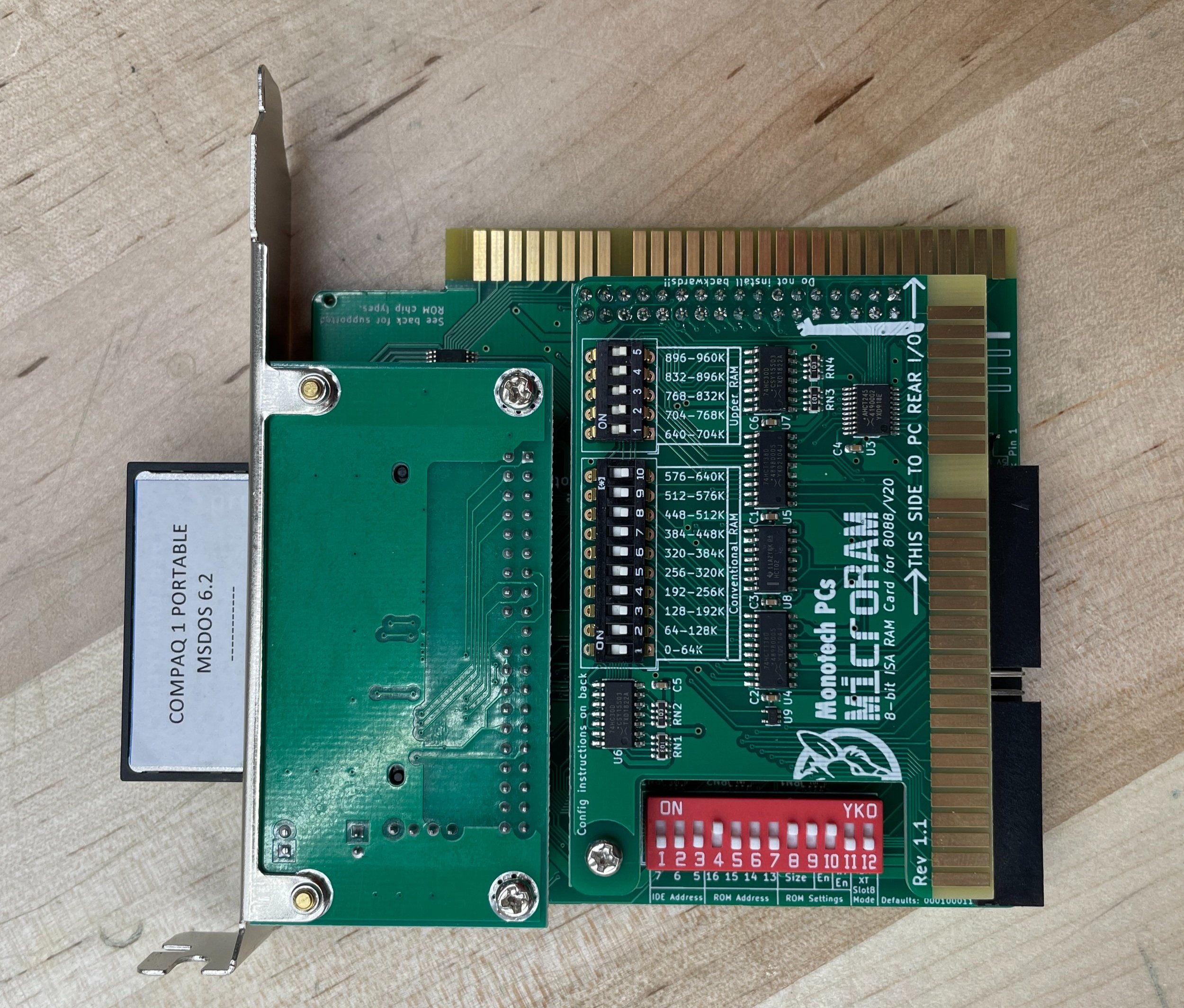
My go-to for older DOS machines is the XT-IDE board. It contains a BIOS extension that the system calls upon boot that installs code to allow these older machines to look for an IDE disk to boot from. (Most of these machines had no original ability to boot from a hard disk. In fact, for some boxes, there was no hard disk invented yet). IBM was smart, however, and they included the concept of the extension BIOS. Machines, from very early on, would look for a ROM at a specific address and run the code if a ROM was found there. The XT-IDE is a modern card designed by enthusiasts to breathe life into older computers.

Installing these boards is very simple. Format at Compact Flash card for FAT and install DOS on it. Put the card in the CF slot on the ISA Card and plug it in. It has literally never been harder than that on any of my older DOS boxes, and the PC4 was no different. I have restored many DOS machines at this point, so I just copy the files from one of the others and start making changes required based on the hardware configuration of each new computer.
A problem did arise using the system for a while. I noticed something I haven’t previously encountered. Using the <CTRL><ALT><DEL> to warm boot the PC would not reset the computer sufficiently to boot again from the XT-IDE without hard cycling the power (i.e., Cold Boot).
On a warm boot, the BIOS (either the Computers or the XT-IDE extension) would report “Error 60h!” and then boot from the floppy. I set this aside as an inconvenience deciding to solve this problem later.
A Solution for the Hard Drive Bezel
The XT-IDE is such a great solution for older DOS computers. However, one complication with this approach was that the front of the original hard disk installed in the NCR was actually part of the bezel design of the system and included the drive activity LED. A closer inspection revealed that the bezel was attached to the original drive and could be removed.
I needed to design a way for the bezel to appear in the front of the machine to restore the machine's original appearance, something that was important to the project.
The bezel had the drive activity LED embedded into its design as well.
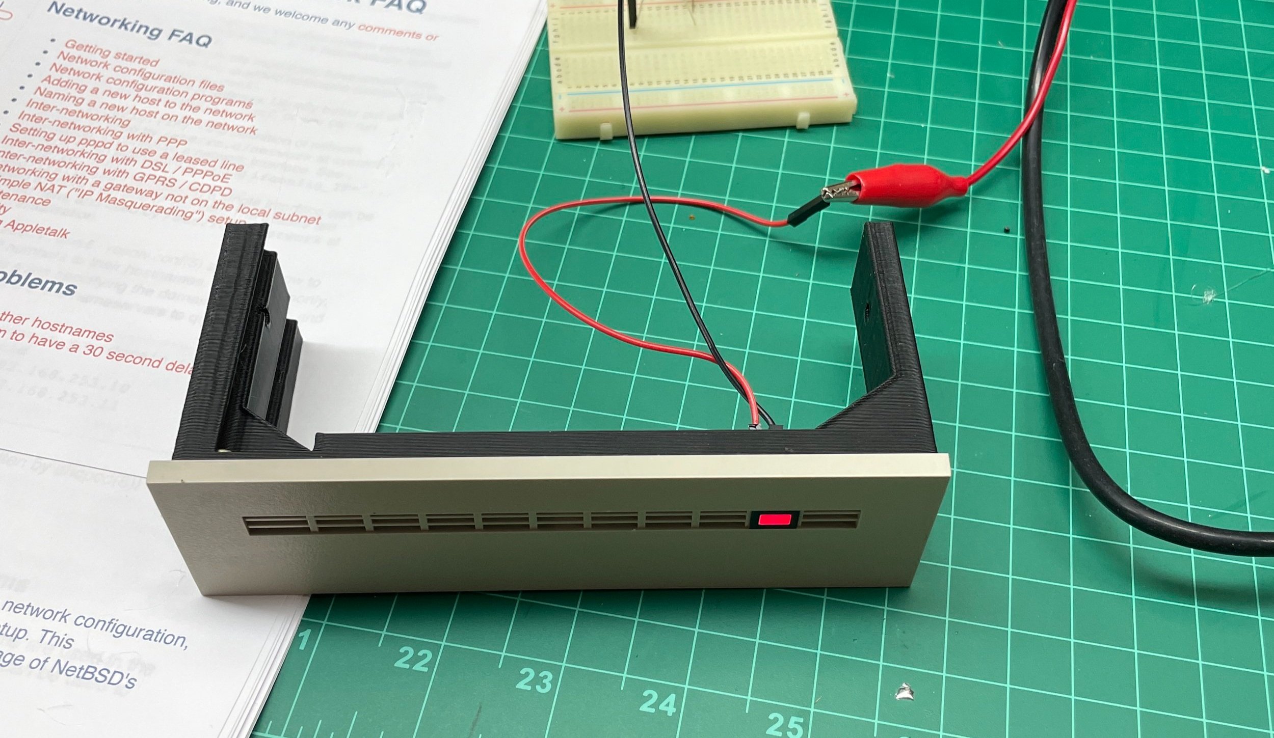
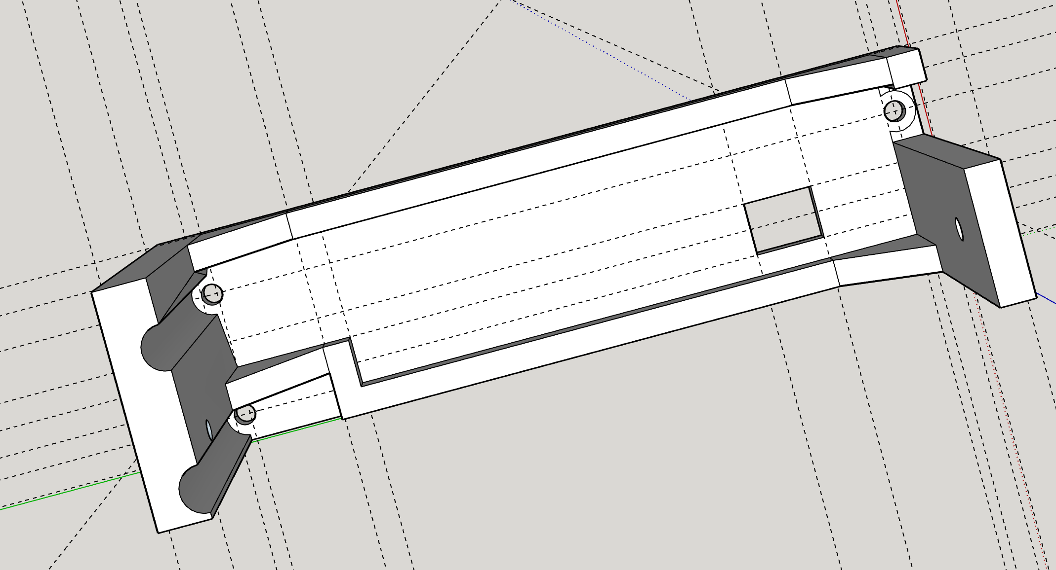
I decided to create a 3D-printed bracket that would allow me to attach the bezel with the LED and mount it in the machine to make it look original. Moreover, I could connect the XT-IDE drive access LED connectors to the original LED in the bezel, making the machine look perfect, and the LED would flash as expected during drive activity. With older machines, having an HD access light was quite useful as they are relatively slow computers by today’s standards. It gives some feedback that everything is working as intended.
After designing the bracket, I printed it and attached it to the bezel, making everything look very original. I tested the original LED on the bench with my power supply. It appeared to work fine.
However, once connected to the XT-IDE it was very dim and if the disk was accessed quickly it was barely visible at all.
At this point, I realized that the XT-IDE supplies a 3.3V output for the LED, while the LED was expecting 5V. In addition, the XT-IDE had some unknown value of current limiting resistor inline as well that all conspired against this solution.

After some thought, I decided to try using a level-shifting IC that would convert the 3.3V to 5V.
I had used these chips in some Arduino projects where I needed to use TTL logic with the lower-power 3.3V Arduino. I had a SN54AHCT125 Quad Bus Buffer Gate lying around, so I tried it, and it worked splendidly
In addition, I decided to replace the 30-year-old LED with a better-performing modern LED and a better selection of current limiting resistor. Using a Dremel tool I ground off the back of the embedded LED until just the lens was left on the front side.
I mounted the board on the new bezel support, and the combination looked and worked flawlessly.
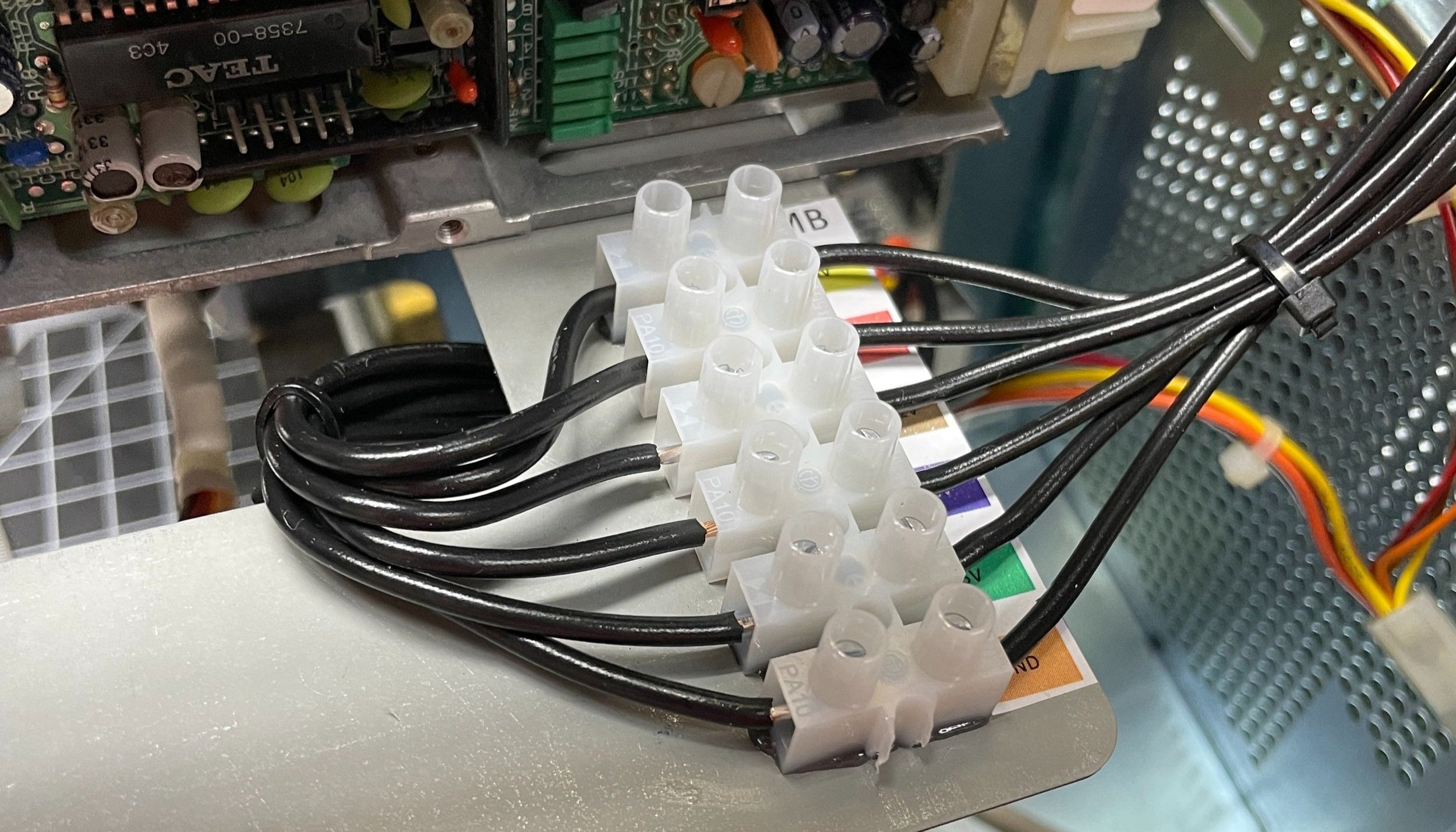
Power Breakout
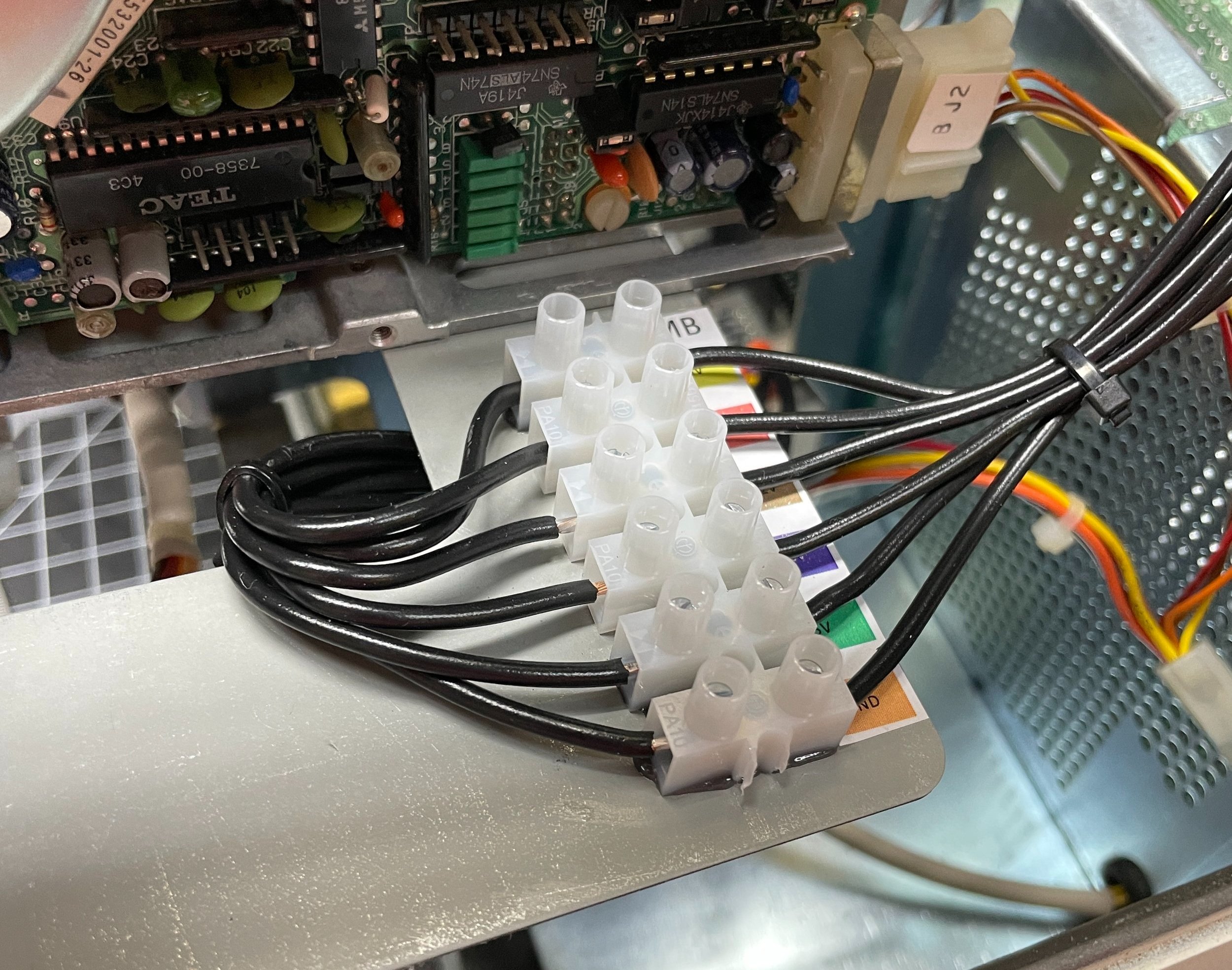
Working on, or even using a voltmeter to check the power supply in this computer is difficult as it’s embedded under the CRT.
With the original Hard Disk removed from the bay, the location made an excellent place to install a junction block for the different power rails before they made their way to the motherboard. I included stickers so would remember what each supply line was, making future testing much easier.
Revisiting the <CTRL><ALT><DEL> warm boot issue.
As explained previously, after a warm boot, the BIOS would report an error 60h and boot from the floppy drive. While cycling power was a temporary workaround, it put a lot of stress on the power supply and, more importantly, on that glorious orange switch!
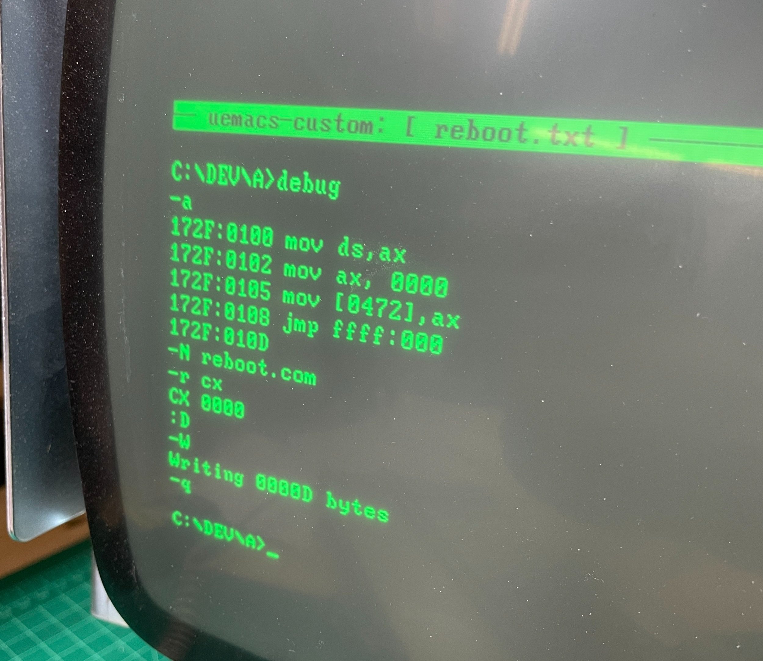
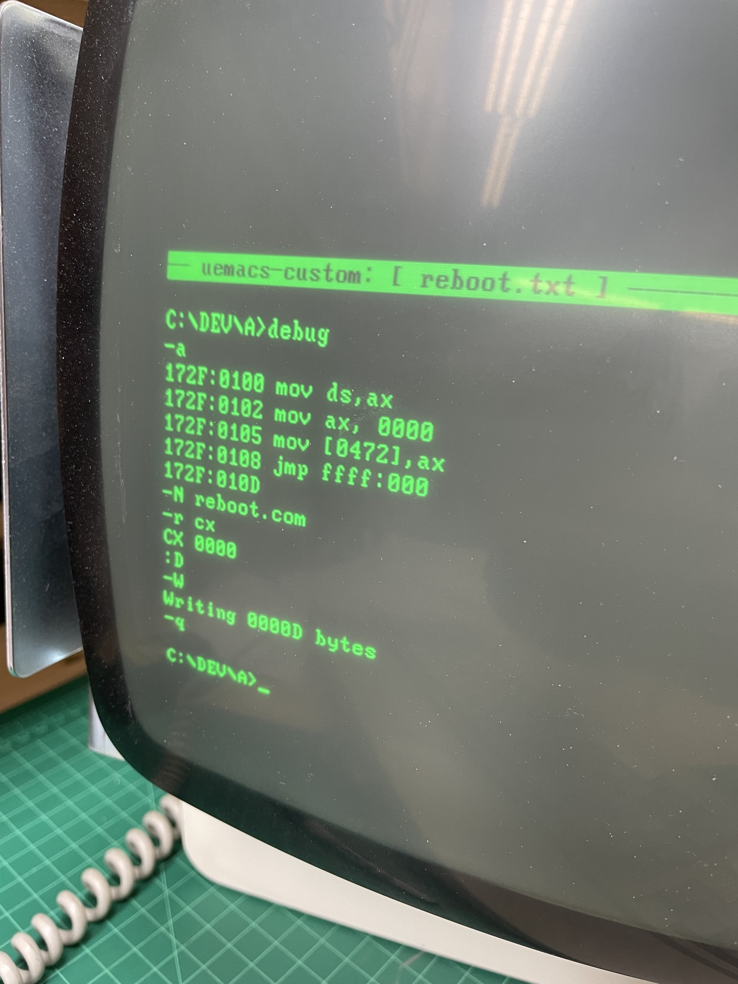
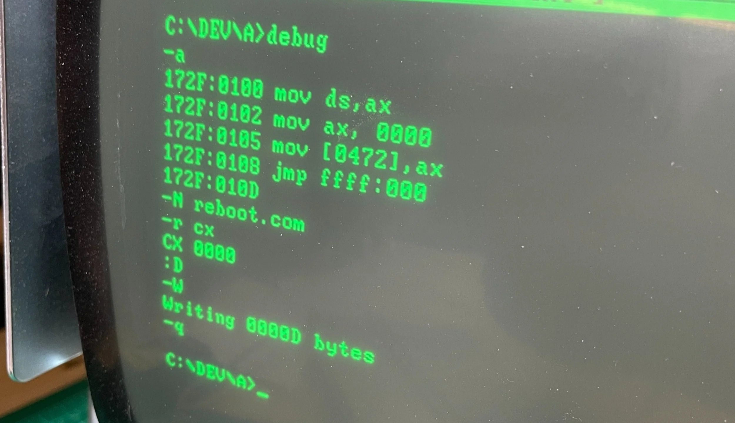
To solve this problem, I created an assembly program to run from the command line to jump the machine to the cold start reset vector when the “reboot” command is entered. It works great if you are at a DOS prompt.
What I really needed was a reset button
The reboot command solution worked well, but if the machine was locked up your really needed to reset button.
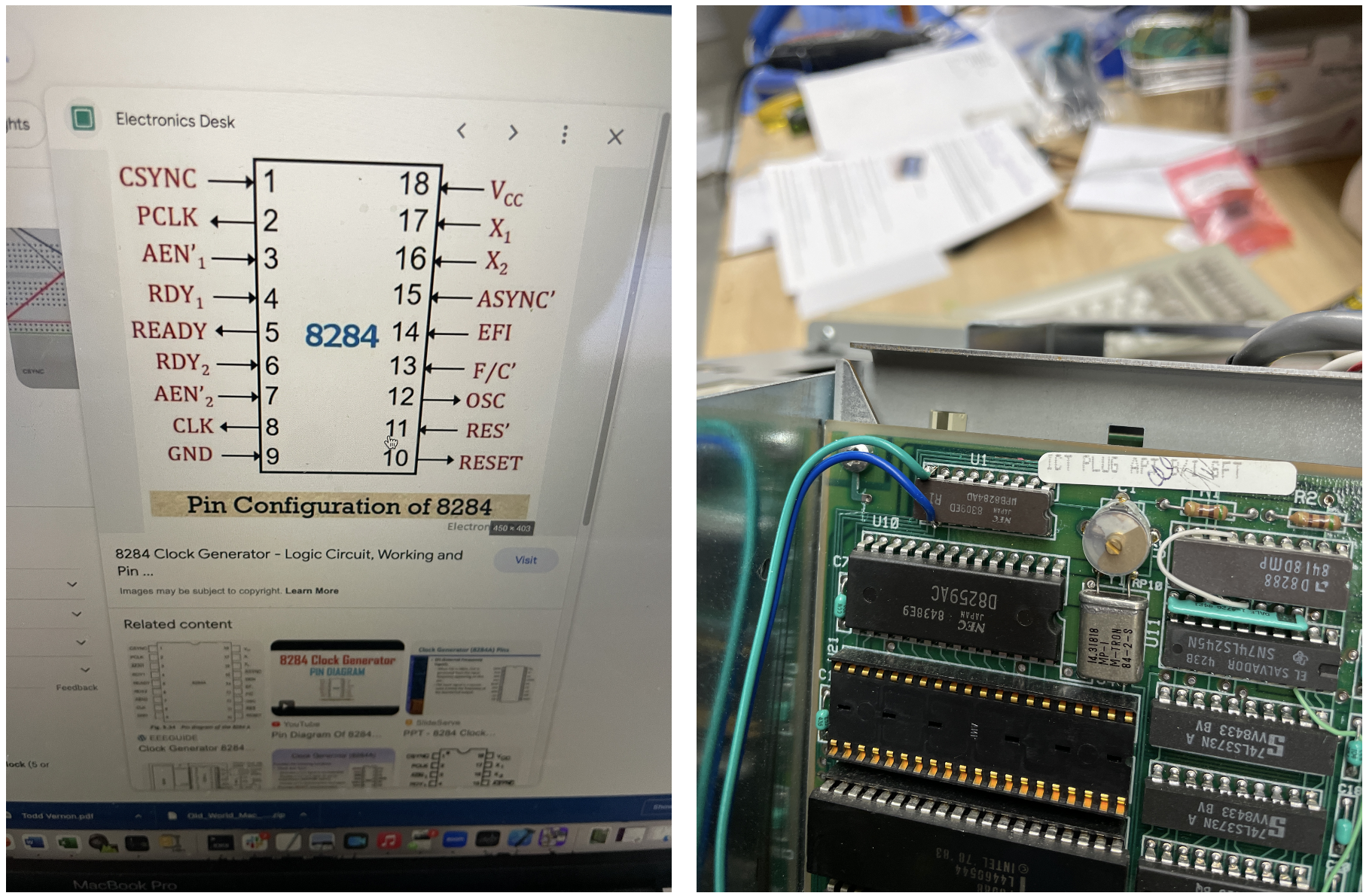
After some research, I found an article from the 1980s on installing a reset switch on an IBM 5150 PC by connecting a momentary switch between GND (Pin 9) and RES (Pin 11) the clock generator IC.
When pressed the machine does a cold boot as if the power had been turned off and back on again.
That solution worked great, so I pressed ahead, finding a hidden place to mount the reset switch to the case.

Installing the reset button
I happened to have a long neck micro switch left over from my restore of the Commodore SX-64, so I fabricated a bracket to affix it so it would barely protrude from the vents below the CRT display.
Attaching the leads to the clock chip was the perfect solution, and its completely invisible from the outside of the machine.

Network Card Addition
The two additions I generally make to my DOS machines are the XT-IDE Flash drive and a network card. The network card is strictly not required as you can install software easily by just moving the Flash Card back and forth via sneakernet, but having networking is nice as I have an FTP server setup on my local network, and it makes it easy to move files around between computers.
In the DOS world, TCP/IP was a new thing back in the day. Network cards existed at the time (mid 80's), but they were a mixed bag, and they were expensive. As DOS was not a multitasking or threaded operating system, most cards were used with early Windows installs that postdated these computers. However, years later, some enterprising software types figured out how to create "packet drivers" for DOS. A packet driver is TSR (Terminate and Stay Resident) program that is run from the command line; it sets up some memory it copies itself into, attaches to the network card via a hardware interrupt, and makes sure DOS doesn't use the memory for the next program, and exits. This way, when the card receives a packet, the interrupt calls the TSR and fills a software buffer other programs can access to communicate. None of this would be helpful without some TCP tools that Mike Brutman had written years ago. Mikes TCP tools (i.e., telnet, FTP, DNS) are standard Unix-type tools with the TCP stack compiled into them. These tools know how to talk to the packet drivers for various cards. When it's all said and done, you have modern networking for old computers. You need to research what cards work and then find deals. Their old cards can go from $20 to $400. I have a stash of $20 ones, so I put one in the 5155.

Real-time clock addition
I like to add a real-time clock to these older DOS machines so they automatically know the time when they are booted up. Machines of this era would have to ask you to enter the current date and time, which sucks. In other projects like the IBM 5155 or Compaq Portable 1, I’ve used a modern fan-produced ISA card with a real-time clock chip and a CR2032 battery. With a few modifications to the autoexec.bat file, everything works great.
The problem with the PC4 was I was out of ISA slots. The PC4 only has five ISA slots, and they were all taken up by things more important than a clock. Interestingly it appears that the original intention was to have six ISA slots, as the metal bracing I mentioned above has a cutout for a sixth but another was not on the motherboard.
Back in the 80s, a company, SMT, started making zero-slot real-time clock chips for these computers to work around this problem of “no slots left.” The chip would incorporate a small coin cell battery, a Dallas Timekeeper IC, and a socket. You would insert the chip into the BIOS socket and then insert the BIOS ROM into the socket on top of the timekeeper.
The timekeeper would snoop the address bus for an address sequence only it would understand. When this sequence of addresses were found along with the OE (output enable) and CE (chip enable), then the embedded chip would start to read one of the address lines going to the ROM as if it were a serial communication line. With the proper software, the rest of the system was oblivious to data transfer. In the same way, the timekeeper could be told to put its data onto the data bus to report the time back upon system boot. During these transfers, the ROM’s CE was held in a state that it would not respond.
It was quite ingenious and required no external address decoding on the motherboard.
A link to the manual that describes its operation in more detail

While you can still find these chips (err, $24 from China), they are all dead as the battery only lasted ten years and is all 30 years old. However, you can breathe new life into the chip by taking a Dremel tool to the chip, removing its battery, and then attaching an external modern coil cell battery to the Timekeeper IC.
Good video on how to do this here (note, mine had only battery embedded)
This is precisely what I did. After obtaining the “Dallas DS1216E” IC, I removed the battery and soldered an external connector onto the IC. I 3D printed a second board with a CR2032 battery holder that snapped into the unused ROM socket next to the BIOS ROM and connected the two with leads for battery power.
The IC that I bought was in pretty rough shape when I arrived. I used toilet bowl cleaner to clean rust off the socket on the chip, then ran it through the dishwasher, and it came out clean and ready to use.
Video on using toilet bowl cleaner here
After installing the required software utility from brutman.com and after setting the time, it worked great the first time. Things never work the first time!
link to the STL for the batter holder board
Link to Software used to set and get the time from the no-slot clock.
Final Thoughts
This project was a lot of fun but also frustrating. I bought the machine on a bit of lark because I think it has such a unique industrial design. As a friend pointed out, “It’s all about the Orange button.”
I always like the machine I just finished the most (usually), but this one is so unique it’s just fun to look at!
The keyboard is quite nice, and the outside is nearly pristine. The screen is clear and readable, and all the parts work well. It is heavy as a beast, however.
Such a great project that forced me to use a ton of stuff I learned way back in school when I didn’t know what I was going to do to make a living. It turned out to be software, but the hardware skills were still in there somewhere!
Gallery