SPARCstation Voyager
The SPARCstation Voyager, introduced in 1994, stood out as a portable computing solution, differing from the traditional laptop. Its notable feature was the capability to run on rechargeable batteries for several hours, making it an ideal choice for those in need of a fully functional UNIX workstation that could be conveniently transported. It found widespread use in scenarios like software demonstrations, where sales engineers could effortlessly carry the machine and set it up within minutes. The Voyager was available in several configurations, including options with black and white LCD, color LCD, or a headless variant compatible with a standard Sun color monitor.

Acquisition
I had been searching for a Voyager for several years. They are not common machines to find and when you do they are often broken and nearly always expensive. The original 1994 price of a color Voyager was around $14,000 or about $29,000 in 2023 dollars.
There are two types of Voyagers available: machines with broken screens and machines with screens on the verge of breaking. Nearly every machine you come across exhibits streaks of dead pixel lines. The machine I found was in working condition but with very little information available. I took a bit of a gamble on it, hoping it would mostly be in working order.
At one point in its life it was owned by a company named DBStar. The internet wayback machine didn’t yield any useful results, but some links go back to Oracle, so I assume the company was a database consulting company that used this machine to go onsite and help customers with database configurations.

Unpacking
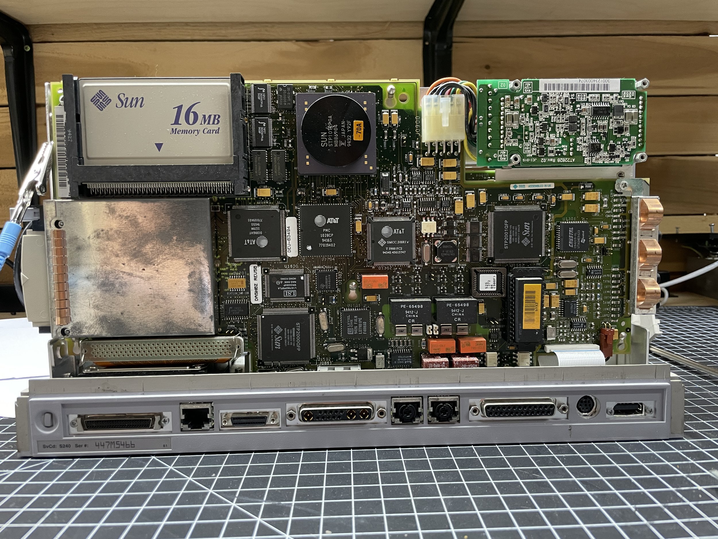
Upon receiving the Voyager, I noticed that it was well-packaged and included the slide-in power supply and the slide-in battery. It's somewhat unusual to have the battery, as I've been told. I haven't done anything with the battery yet, as I assume its life expectancy has long since passed. The machine had 32 MB of RAM, 16 MB on the motherboard, and 16 MB on an original proprietary Sun branded memory card that's about the size of a PCMCIA card.
To my surprise, the machine sprang to life, booting from its small SCSI laptop drive. Furthermore, to my amazement, the screen was somewhat functional. It would fade in and out, but there were no dead pixel lines.
Unfortunately, I didn't have the login information for the machine at this point, so I was somewhat stuck. However, I remained optimistic that the device was in good condition.
Configuration
• 60-MHz microSPARC-II Processor
• 32 Mbyte of RAM
• Chassis dimensions are 5.5- by 14.5-inch
• External SCSI Port
• Internal mini laptop-style SCSI port
• Built-in twisted-pair Ethernet
• Onboard ISDN support
• 1024x768 active matrix color LCD
• Compact Type 5 keyboard
• Infrared port for communications with PDAs and palmtop computers
• PCMCIA expansion for modems, network options, and storage cards
• Serial port

Condition
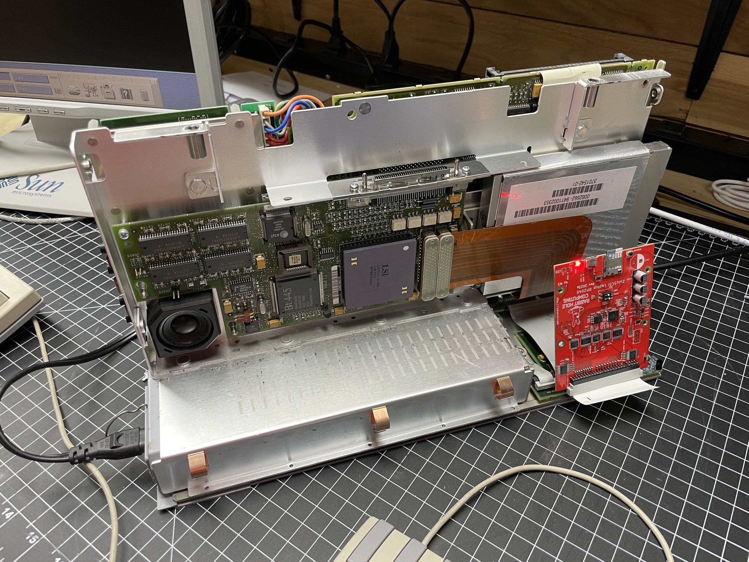
The machine would boot up from the internal laptop-style SCSI hard disk. However, due to a lack of credentials, I couldn't proceed any further. I observed that the drive made a clunking sound every few seconds. This noise could be attributed to the heads being parked due to inactivity or the drive being on the verge of failure. Nonetheless, it didn't concern me much, as I intended to replace the hard disk with a ZuluSCSI hard disk emulator. Inertial Computing makes a laptop version that fits perfectly in place of the original disk, and I acquired one from their website.
The internal LCD screen posed a bit of a mystery. When it worked, it displayed impressive brightness and clarity, but unfortunately, it never remained operational for an extended period.

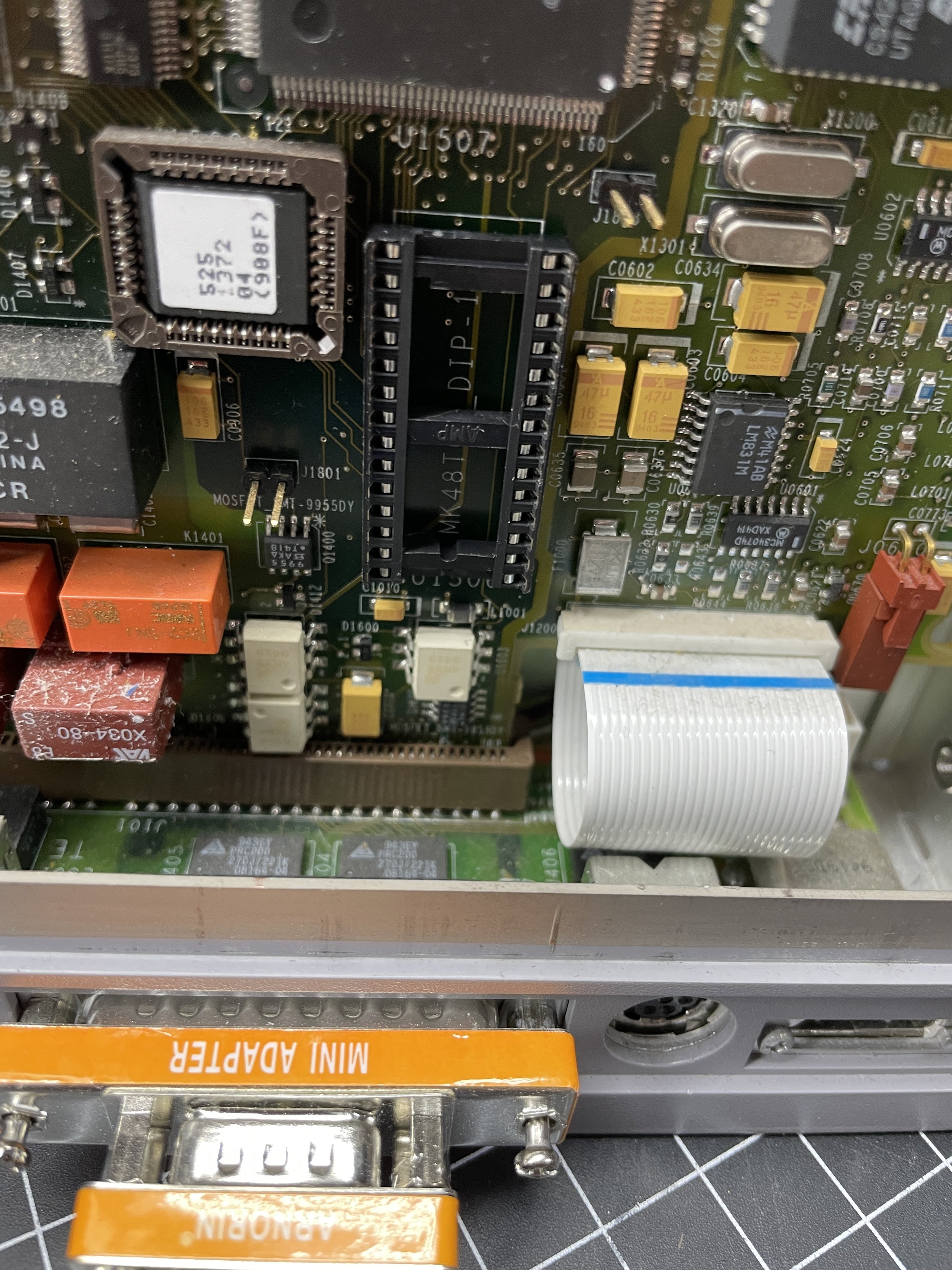
Timekeeper Update
Like all Sun Workstations, the timekeeper chip was dead and needed to be replaced. The Voyager uses a M48T08-150, which I believe is out of production.
The timekeeper chip performs a few functions in a Sun Workstation. The first is to keep the time when the power is turned off or removed from the machine. In addition, Timekeeper chips have a small amount of memory that the host machine can use to store certain parameters. In a Sun Workstation, that memory is generally used to store the machine ID that is used by the OS when booting, as well as holding the ethernet address.
When the battery finally goes dead, usually after a decade or so, the chip needs to be replaced. Different workstation models use different timekeeper models, but they are quite similar. Many chip models are no longer produced, so it is common to use a Dremel tool to grind away the bottom of the chip and attach a new coin cell to the exposed leads. Once this is complete, the chip needs to be reprogrammed using the OBP software built into the Sun ROM.
I was fortunate enough to already have a modified chip that a friend had given me, so all I needed to do was replace the chip with the one I had and then reprogram the information.

Hard Drive Replacement
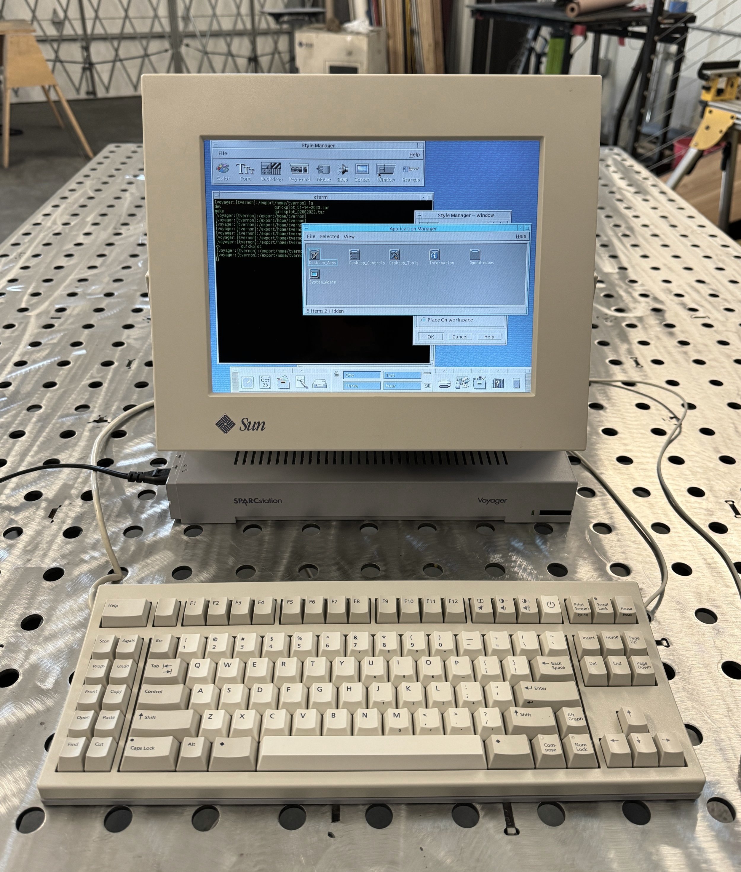
Instead of immediately addressing the screen issue, I concentrated on getting the ZuluSCSI emulator functional and booting Solaris. Since I have several systems running Solaris 2.6 on Zulu boards, I opted to copy one of my Solaris 2.6 images onto a mini SD card and give it a shot. To my delight, the machine booted up promptly. Solaris 2.6 worked great with the Voyager and even presented the hibernate menu item that is unique to the Voyager from the CDE shutdown menu.
I ran the Voyager for a few days with an external monitor attached, and it proved to be highly stable and surprisingly fast on my standard compiler tests.
Disassembly
From the onset, I was cautiously optimistic that I could get the original LCD panel to work. The problems seemed manageable, and my initial suspicion was that failing capacitors might be the issue. Monitors attached to the rear of the machine worked fine, and according to the Voyager Service Manual, the rear display and internal display use the same graphics card. The rear display port worked, so I could rule out the video card as the likely problem.
In the back of my mind, I also considered the possibility of replacing the nearly 30-year-old LCD with a modern one, a modification I had successfully undertaken in my Commodore SX64.
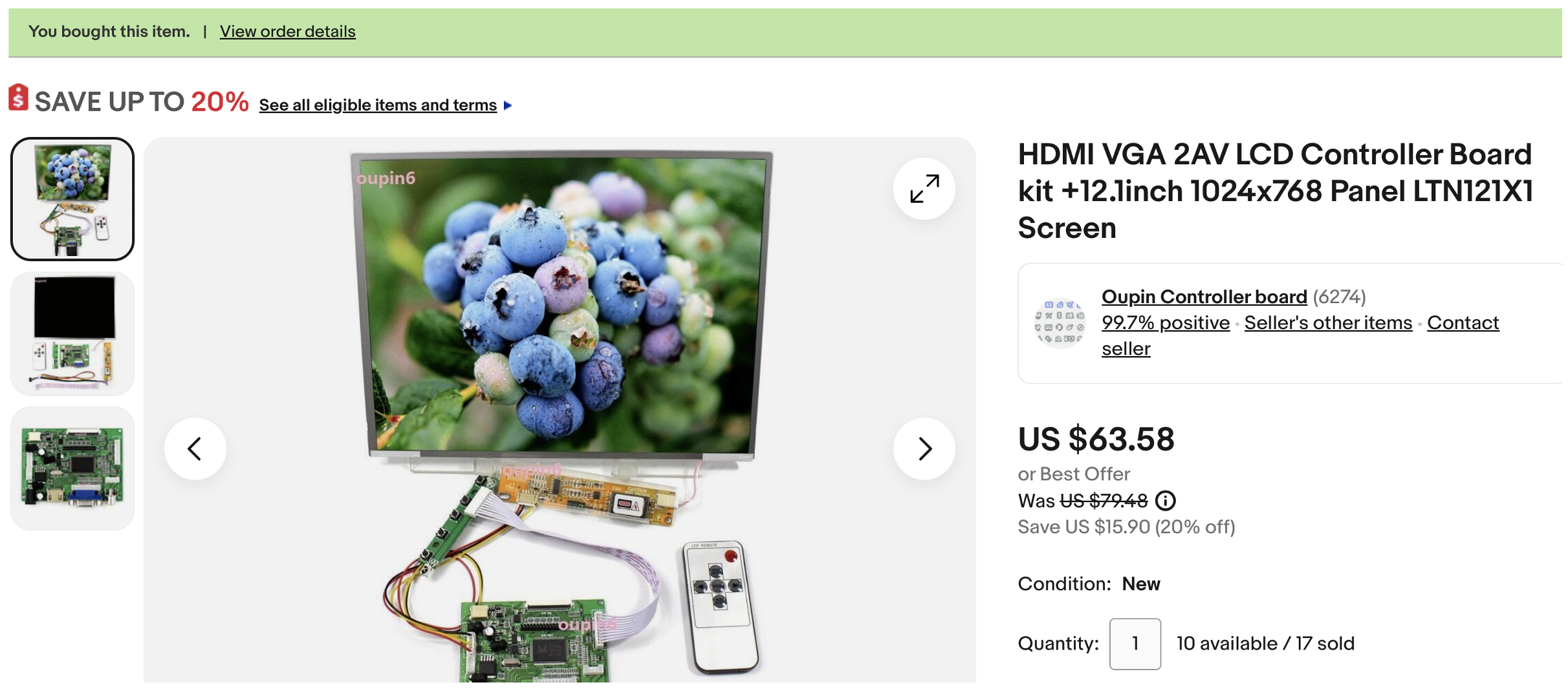
A new modern LCD isn't that expensive; I believe I paid $60 for a new 12.1 1024x768 screen with a controller on eBay, so I decided to order one just in case, as the lead time on these is often 30 days or more from China.
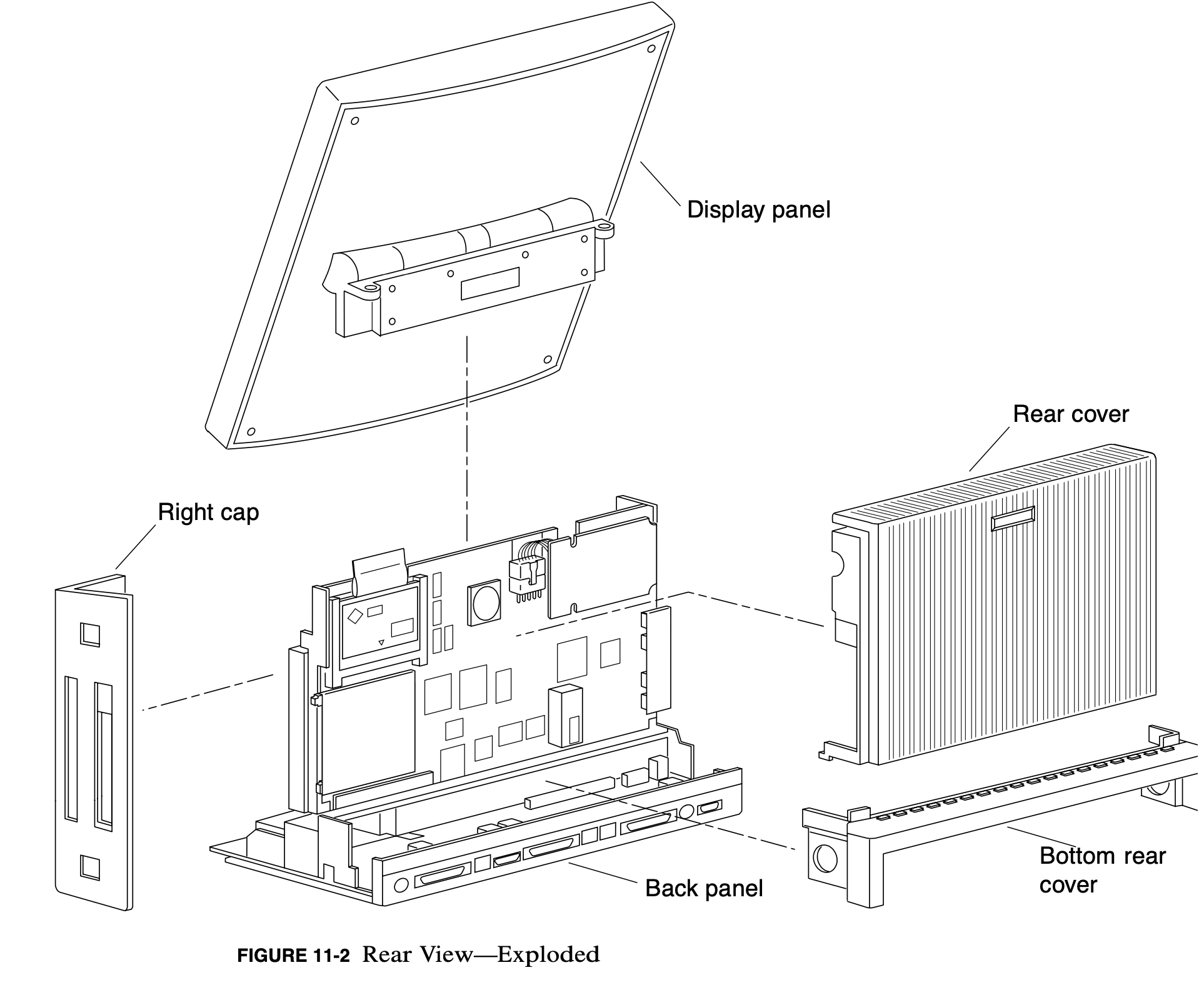
Disassembling the Voyager and its screen was a somewhat time-consuming and intricate process. I highly suggest grabbing the Voyager Service Manual and following the disassembly and reassembly instructions, as there are plastic bits that could easily be broken if you don't perform those tasks correctly.
I knew I would have the Voyager disassembled for some time, so I carefully placed the specific screws and specialty parts in envelopes with their purpose written on each envelope. I started to adopt this process when I disassembled the NCR PC that I restored last year. That computer used so many different screw sizes, thread pitches, and lengths that it was clear that trying to remember all of that would be futile. I've also learned that even with the best intentions, the parts get lost after a few months.

Attempting to fix the original LCD panel
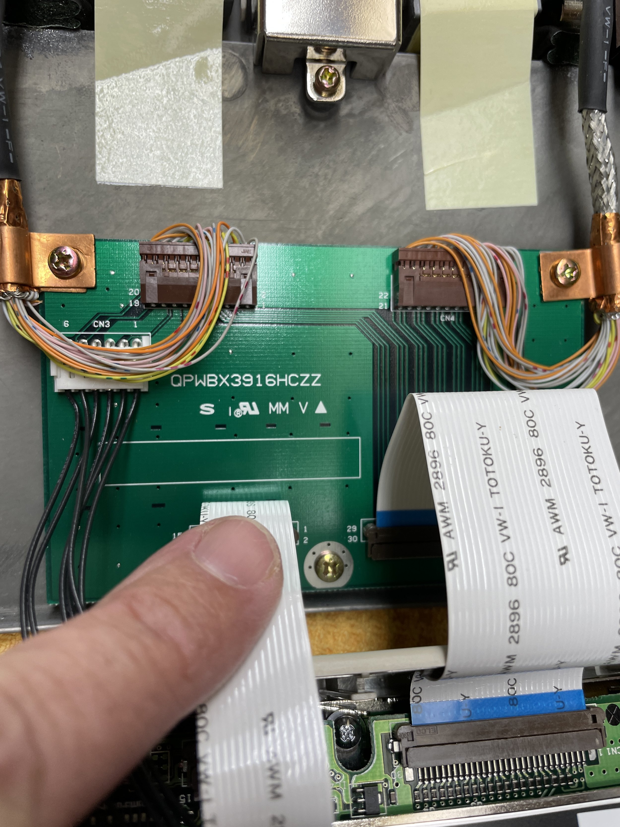
The screen assembly is easily removed with two screws that attach it to the top of the Voyager. Voyagers were sometimes sold without a screen, and, in that case, a plastic part is installed over the connector. The electrical connections are routed through a very large micro-pitch DSub-looking connector with 68 pins. All video, as well as +5 and +12 power, routes through the connector.
Once I separated the screen assembly from the system, I made a few observations. When I initially noticed the screen flickering and fading in and out during operation, I suspected it might be related to the backlight. However, after disassembling the machine and the screen assembly and running it on the bench, I realized that the backlight was consistently functioning well. In fact, the screen uses a fluorescent backlight. Fluorescent fixtures generally don’t dim, and the backlight was completely functional. Upon closer inspection, the issue appeared to be related to the changing opacity of the pixels, which indicated a problem with the LCD controller board.
Upon removing the controller board from the back of the screen assembly, I discovered several failing electrolytic capacitors with leaking liquid. Using my trusty magnifying glass, I recorded the values of all the visibly failing capacitors and ordered replacements. I did not try replacing capacitors that looked fine.
Once the new capacitors arrived, I carefully removed the old surface-mount caps and replaced them with the new ones. Powering the system back up resulted in a significantly improved image, although some issues remained. I left the machine running for a few hours, but upon returning, the screen had deteriorated further. Unfortunately, I couldn't get it to work correctly again, and it would consistently go to bright white shortly after booting, with a distorted image fading into white. In addition, it now had the telltale pixel lines that eventually appear on all Voyagers.
At this point, I decided to call it quits on the original screen and proceeded to explore the replacement option. I’m glad I was able to see the original screen working for a bit of time. It was very nice, and I’m sure at the time it was designed, it was quite expensive.
Moving on to the replacement LCD panel
As mentioned earlier, I had already ordered a modern LCD screen when I first received the computer. I had a feeling that if fixing the original screen were a straightforward task, there would be more information available online regarding the process. I found none in my searches.
While there is an abundance of low-cost, high-quality LCD screens available on eBay, Alibaba, and even Amazon these days, they primarily support VGA (analog) and HDMI (digital) standards, and not the unique, non-standard, custom format of the Voyager screen. It would be a substantial engineering effort to adapt the digital interface to modern analog VGA screens and frankly way beyond my ability.


Digging into the substantial 68-pin connector that linked the screen controller on the back of LCD panel to the video card in the Voyager, I quickly realized that the screen utilized a parallel digital interface, which posed a problem.
The labeling of the RGB bits is unusual, for instance Green is G0, G1, G2, G3, G10, G11, G12, G13. There are 8bits as you would expect (8bit color) but why do they jump from G3 to G10 and continue. If you have idea why this is the way it is feel free to use the link above to send me an message, I’m just curious.
Setting that aside for a moment, I decided to experiment with getting the new LCD panel to function via the rear 13w3 video connector.

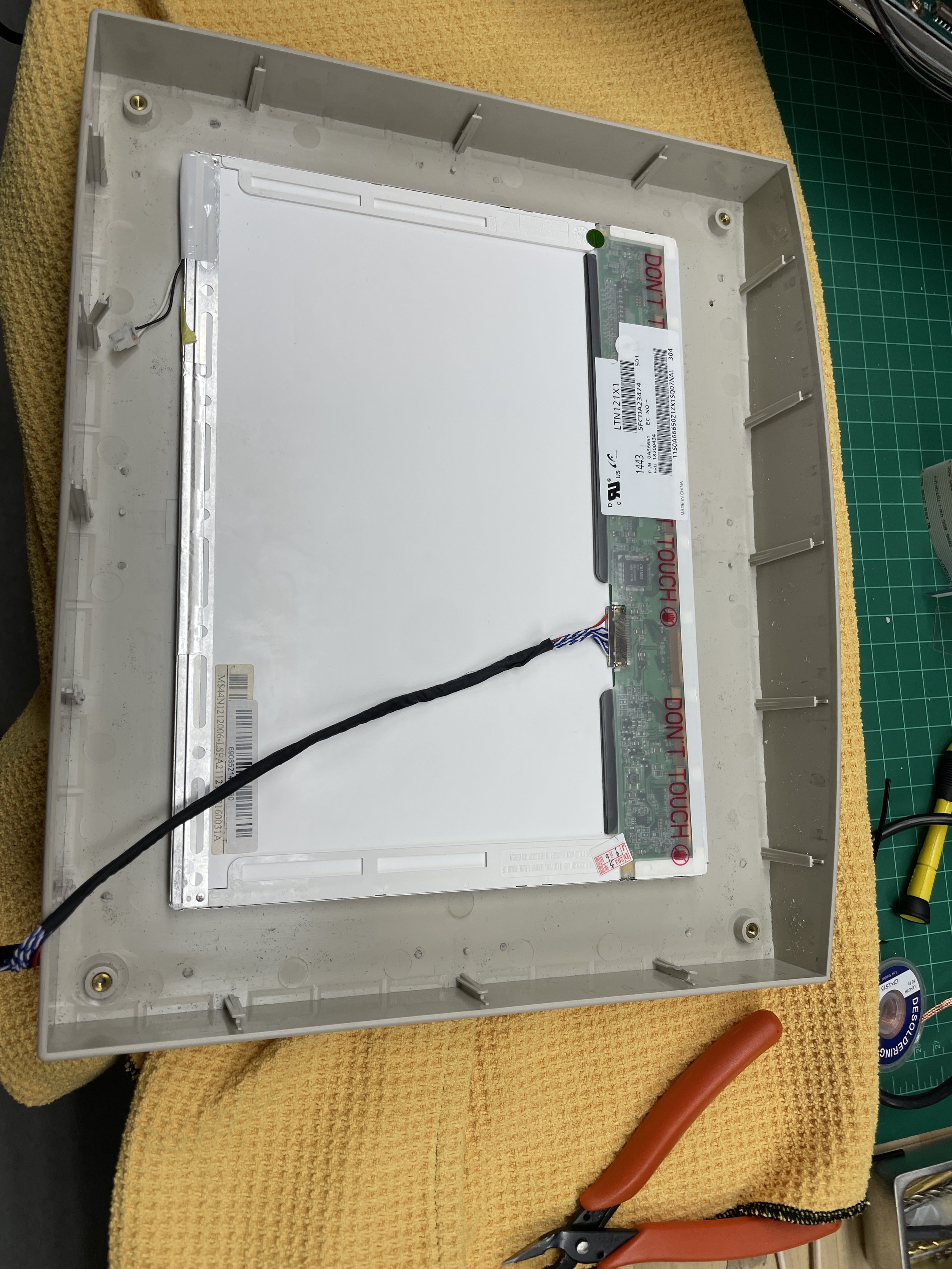
I had acquired the 12.1” 1024x768 panel with a controller board, which matched the resolution and physical dimensions of the original LCD panel. However, I soon realized that the external 13w3 video connector was by default Sun's standard 1152x820 resolution. This resolution was too high for the LCD and was unlikely to synchronize properly. Both concerns proved to be accurate. I looked for 1280x1024 panel but they are not available in 12.1 format that fits the Voyager screen bezel.
After some research, it appeared that the Voyager might support a 1024x768 resolution on the external connection, just as its internal graphics connector did for the original LCD display. The Voyager uses the same graphics card for both the internal and external displays. If you connect the external display, the internal display is ignored, except the backlight remains on.
Information I obtained said the 1024x768 resolution was supported at a 77Hz update rate. I tried that with the new panel, and the panel complained about that frequency being out of its range.
Possible solutions were starting to narrow. After some more research, I discovered that other Sun graphics cards in the same family supported an undocumented resolution of 1024x768 at 70 Hz. While this was a bit of a long shot, I tried it and it worked. The screen could sync up and seemed to work fine.
Originally, I constructed a cable using only the RGB signals and their respective grounds. Upon first inspection, this seemed to work fine. After a bit of playing around with the system, I noticed that the screen would lose sync when the Xserver would start. If I power-cycled the screen after the Xserver started, I noticed the screen would reacquire sync. Sun machines emit a sync signal on the green component signal, and while the panel seemed fine with that on boot-up, I believe it failed to reacquire sync if the image on the screen changed dramatically.
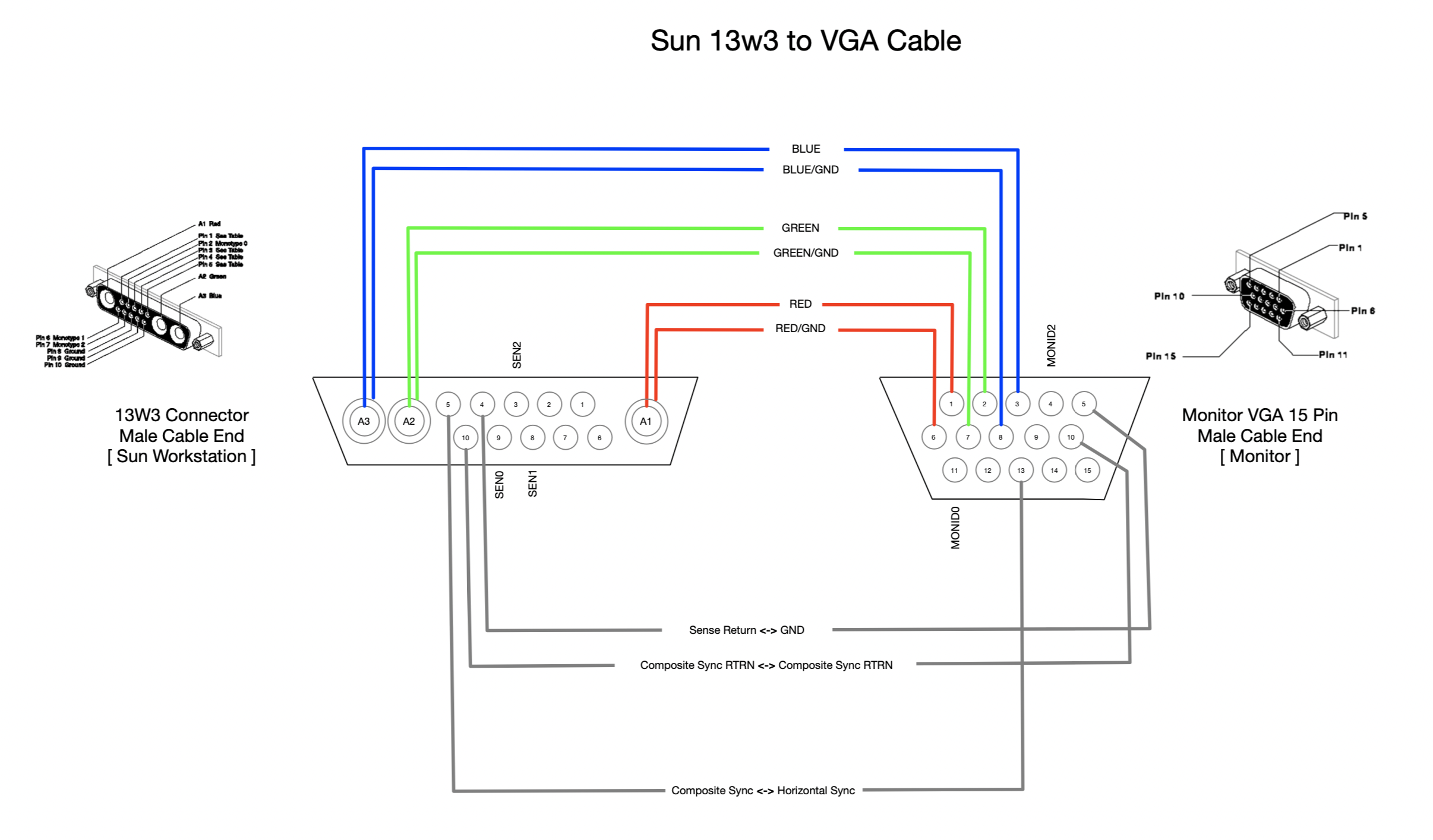
More research uncovered that the Voyager also outputs a horizontal sync on one of the other pins on the connector. After connecting that signal to its VGA counterpart, everything seemed to work fine. I believe transitioning to all black pixels would throw the sync off, and without the horizontal sync line, the panel could not, or would not, reacquire. I’ve included the wiring diagram for the cable I ended up using that worked with this panel and controller.

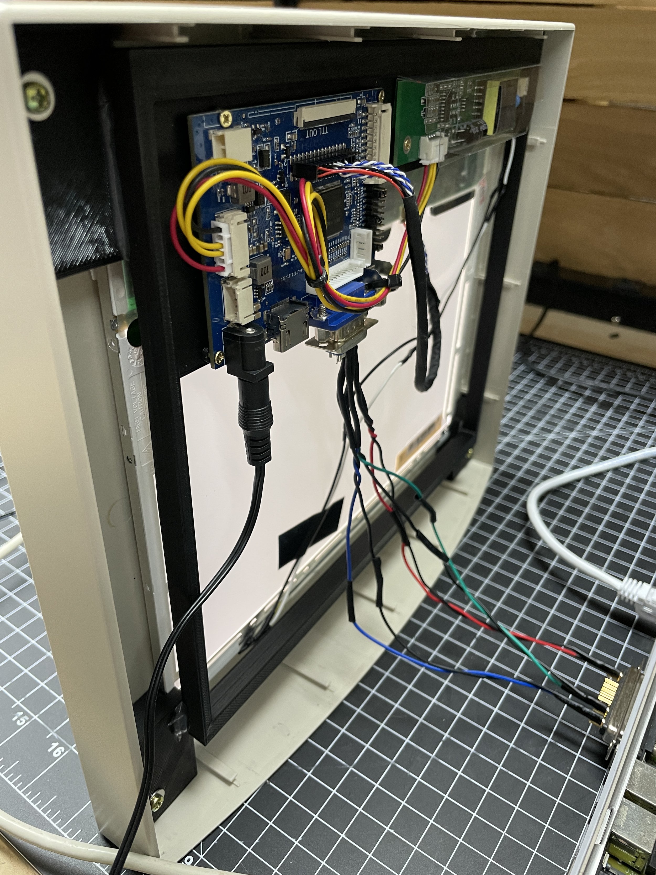
Powering the new LCD panel
Having successfully resolved how to make the modern LCD work with the Voyager, I needed to find a way to integrate it seamlessly into the Voyager's compact chassis. Up to this point, everything had been spread out on the workbench. The Voyager's interior space is limited, to begin with, and often to debug the system would require parts precariously connected on the bench during operation.
The new LCD screen required two things: a VGA signal and 12V power. Finding the 12V power source was relatively straightforward, as it was available on the breakout board that previously fed the original LCD controller in the screen assembly. It wasn’t labeled but it was obvious on the breakout board that the white connector fed power to the original LCD panel. Left to Right the pins were GND,+5V,+5V,GND, +12V +12V. I ended up using the GND toward the middle and the far right +12V. Note that the +12 was closer to +15V but seemed to work fine.
Not all voltages were accessible on that connector without a screen attached, but fortunately, the +12V and GND pins seemed to be active without the original screen attached and those are the only two I needed as the new controller and panel formulated its own voltages from a single 12V supply.
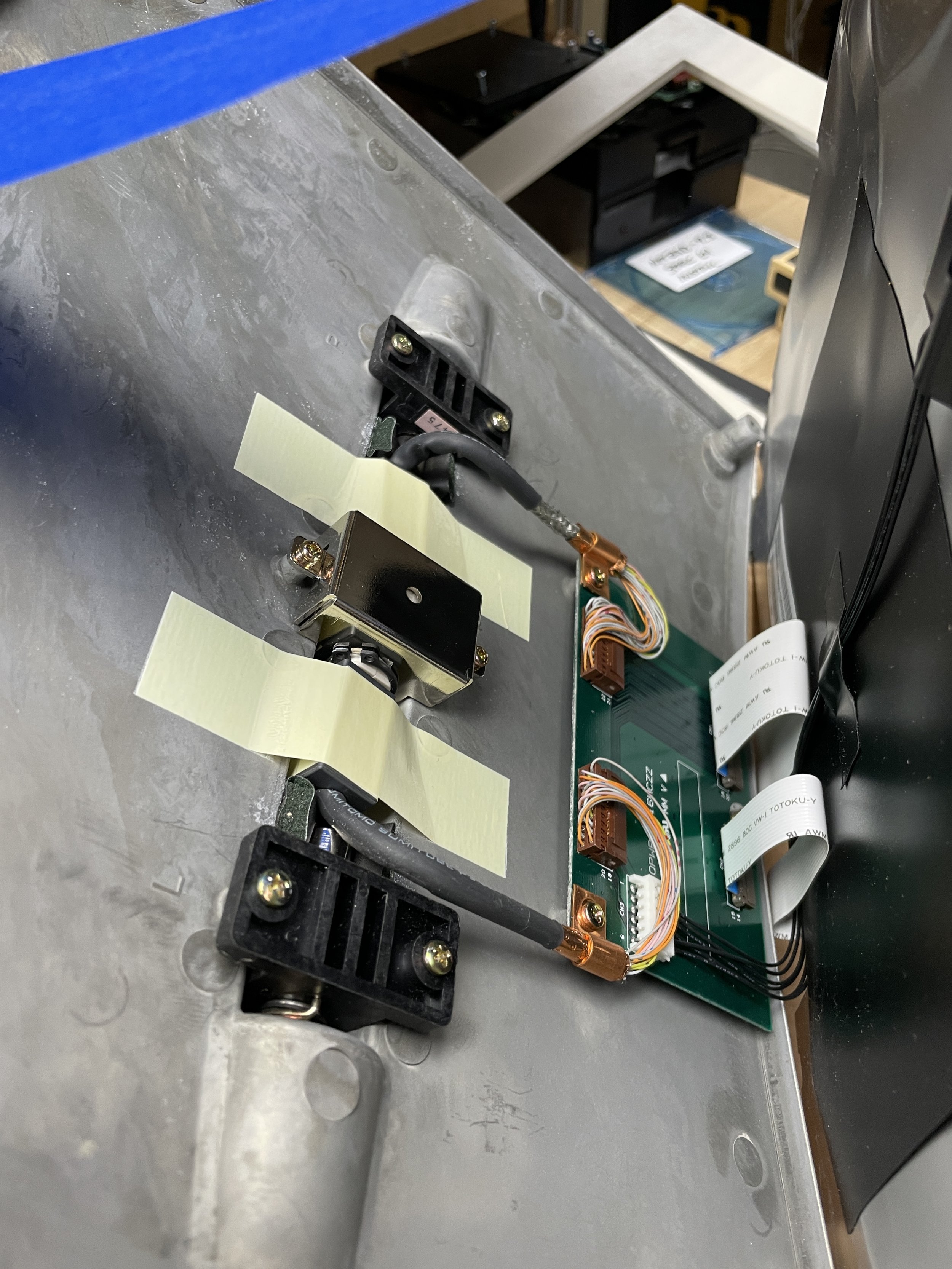
Before connecting the new panel and controller to the Voyager's existing power supply through the internal screen assembly connector, I wanted to assess the power consumption of the original screen. The wires that breakout the 68-pin connector are quite small and could probably not support too much current.
I assumed that the modern screen would draw considerably less current than the original as the modern screen uses a LED backlight design rather than fluorescent backlight.
I connected the original screen and booted the system. The backlight was likely the highest current draw, and it worked fine on the original screen, so I measured the 12V current, and it turned out to stabilize around 900mA. On my bench, I connected the new screen and controller to my bench power supply and measured that the new panel and controller drew about 600mA. This was as expected and good news, meaning it would work but also give the 30-year-old power supply and DC-DC converter in the Voyager a little extra headroom during operation.
Routing the VGA signal to the new panel
Getting the new VGA signal routed to the display was a bit more complicated. The native screen connector was not suitable for these signals, as it was directly attached to the graphics card in the Voyager. On the display side, I decided to create a new wiring path behind the screen, hidden from the user's view, which would still allow for screen articulation.
In order to run the video signal internal to the Voyager, I needed to remove the floppy drive as there was a passthrough available in that location from the backside of the machine to the front side of the machine. This was not a problem as I intended to mount the ZuluSCSI board in the floppy location for easy access to the SDCard. I now had a path from the front of the machine adjacent to the articulating screen assembly to the rear of the machine where the 13w3 external video connector was.
Originally, my plan was to solder the VGA connections to the backside of the original 13w3 connector internal to the computer. While this may have been possible, it seemed risky to execute as the connections are VERY small.
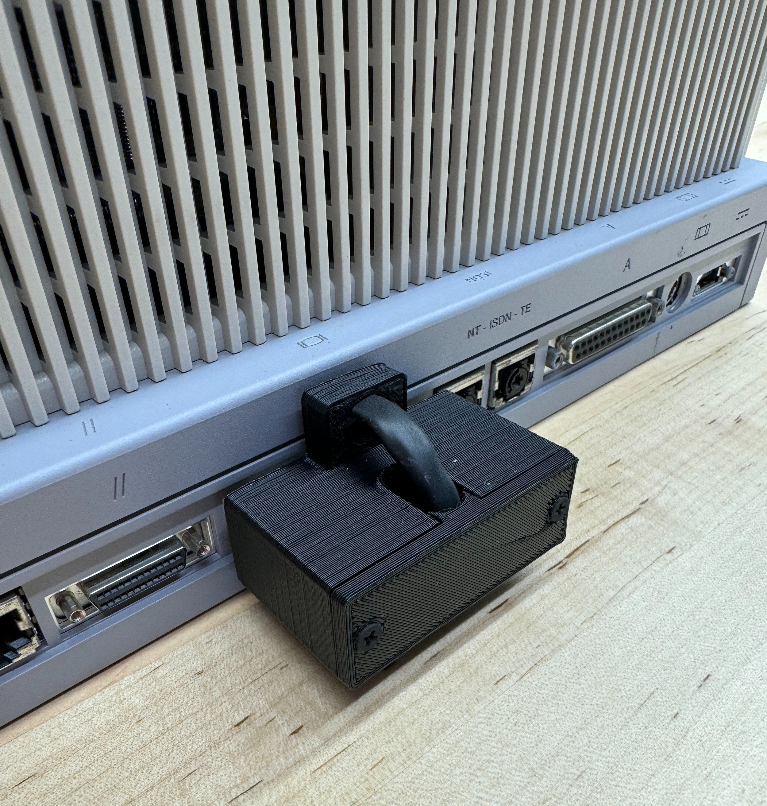
Instead, I opted to 3D print a housing for the mating 13w3 connector that would loop the signals back into the computer. It was a little makeshift but works. I may someday go back and do the more extensive surgery, probably with a microscope, to remove the dongle from the back of the system.

Routing the VGA signals from the internal cable to the screen required a different approach. I couldn't use the internal connector, so I decided to route the signals from the front of the Voyager behind the screen to the rear of the screen assembly inside to the video controller board. This approach worked well and did not affect screen articulation.

Fitting the new LCD panel to the screen assembly
I was reasonably sure that physically the new screen and controller would fit in the Voyager bezel. Modern LCD displays use LED backlight and are much thinner and lighter than the original display. The controller, however, being more capable, was a bit thicker than the special-purpose controller integrated into the original display. After some design work in Sketchup, I was able to make a display adapter that held the new screen in place using the existing display mounts in the bezel and also held the display controller and the display power adapter board. It took a bit of trial and error to find a way that it all fit in the screen bezel assembly but I was eventually successful.
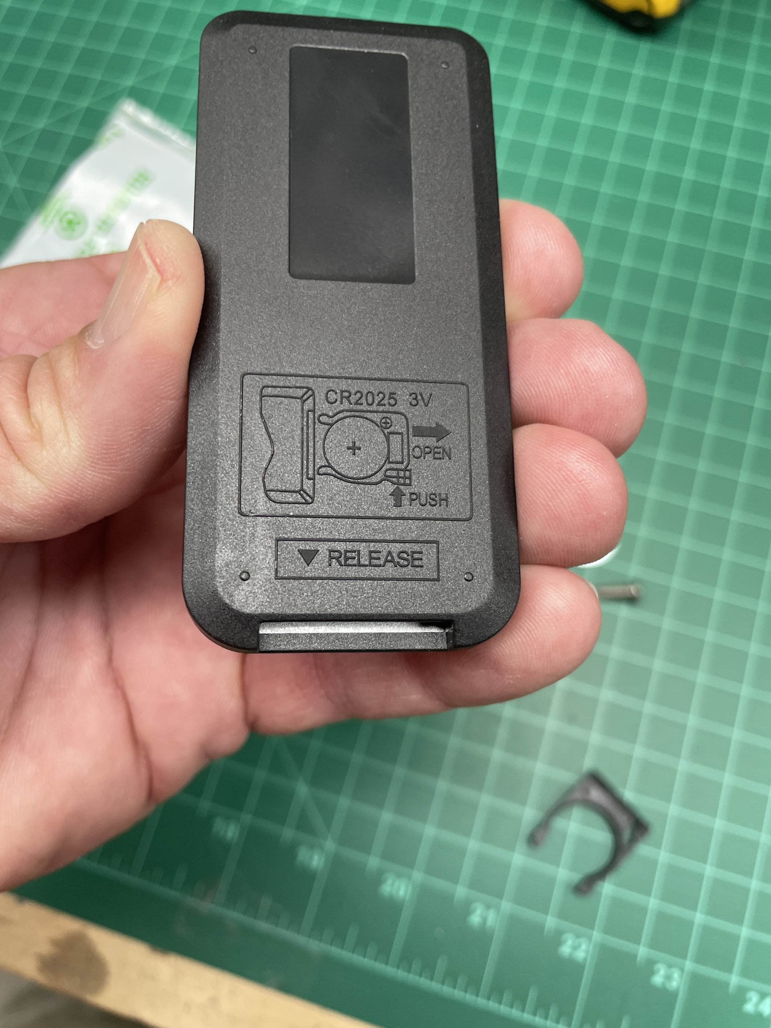
In addition, the controller came with a small user input board that lets you adjust the screen image contrast, color, etc. Using the buttons on this board represents the worst interface you can imagine. The controller also contains an IR sensor as well as a small remote that makes these changes easier. I elected to drill a small hole in the bottom of the screen bezel out of sight for the IR sensor to sit so the remote could be used to adjust the screen on occasion.
Link to Controller Board Mount Frame STL file
(glue to blocks below for a complete assembly)
Link to Screen Corner Mounting Block STL file
(print four with mirrored geometry)

Accessing the SDCard through the floppy slot
I really wanted access to the SDCard with the machine closed up. I generally place the Zulu board in the floppy drive area, allowing SDCard access through the floppy slot. That solution might have worked with the Voyager as well except there wasn’t enough room for the 50-pin ribbon cable to fit into the floppy bay from the hard drive bay below it.
Instead, I opted for an SDCard extender available on Amazon that connects to the micro SDCard slot on the Zulu board and extends through a micro-ribbon cable to a full size card slot housed in plastic. After some design and 3D printing work, I developed a design to secure the SDCard extension slot in the floppy bay and attached it to the Voyager right side plastic assembly.

Closing up the patient!
Getting everything to function on the workbench and getting it all to work within the constraints of the Voyager are two distinct challenges. I made the mistake of connecting and mounting everything without testing along the way. When the machine booted, it raised an error regarding the SCSI terminator fuse. To maintain my composure, I decided to take a break and had lunch.
After lunch, I resolved to tackle the SCSI issue. I once again disassembled the entire chassis of the Voyager, requiring the screen to be removed again. I took this opportunity to reassemble everything adding some wire ties and a few bits of hot glue to secure cables and connectors.
During the reassembly I noticed that the 50 pin SCSI connector had been shifted one pin to the right. Apparently, this made the Voyager think its SCSI termination power fuse had blown producing the error at boot. At each stage I booted the system and indeed the SCSI cable was the problem. I then proceeded to put the machine back together and it worked flawlessly.

Conclusion
This project has been a massive amount of fun. It took about three months to complete. I didn’t know what exactly I was in for when I started the project. To be honest, I was biased toward replacing the screen with a modern LCD panel but I would have postponed that if I could have fixed or original screen. Nothing I did precludes fixing it in the future however.
There are certain machines that have chronic problems and even when they work, you are constantly concerned that by using them you are shortening their life. I felt this way about the Voyager and feel better using a less perishable version that I’ve constructed. The panel I used was good, but not great. I’m temped to find a better model and now that I’ve proven the design it should be easy to retrofit.
The Voyager is pretty fast, fun to use, and I really didn’t want the inevitable death of that LCD screen hanging over my head. I really feel like this machine can now go another 30 years. Probably not the power supply however, it’s always the power supply!
Gallery