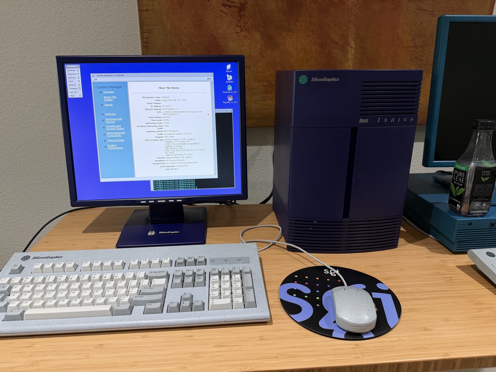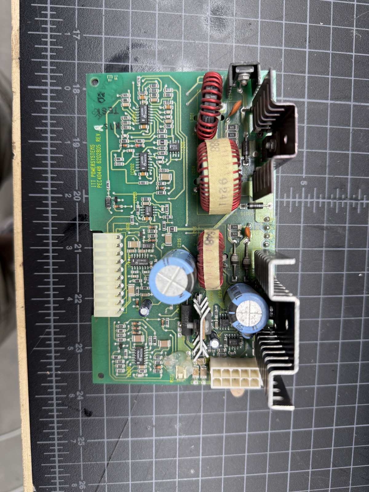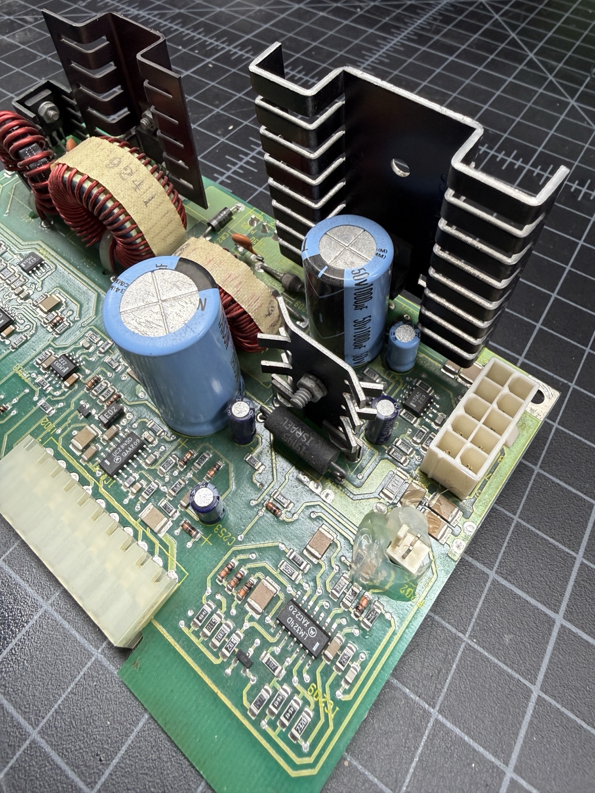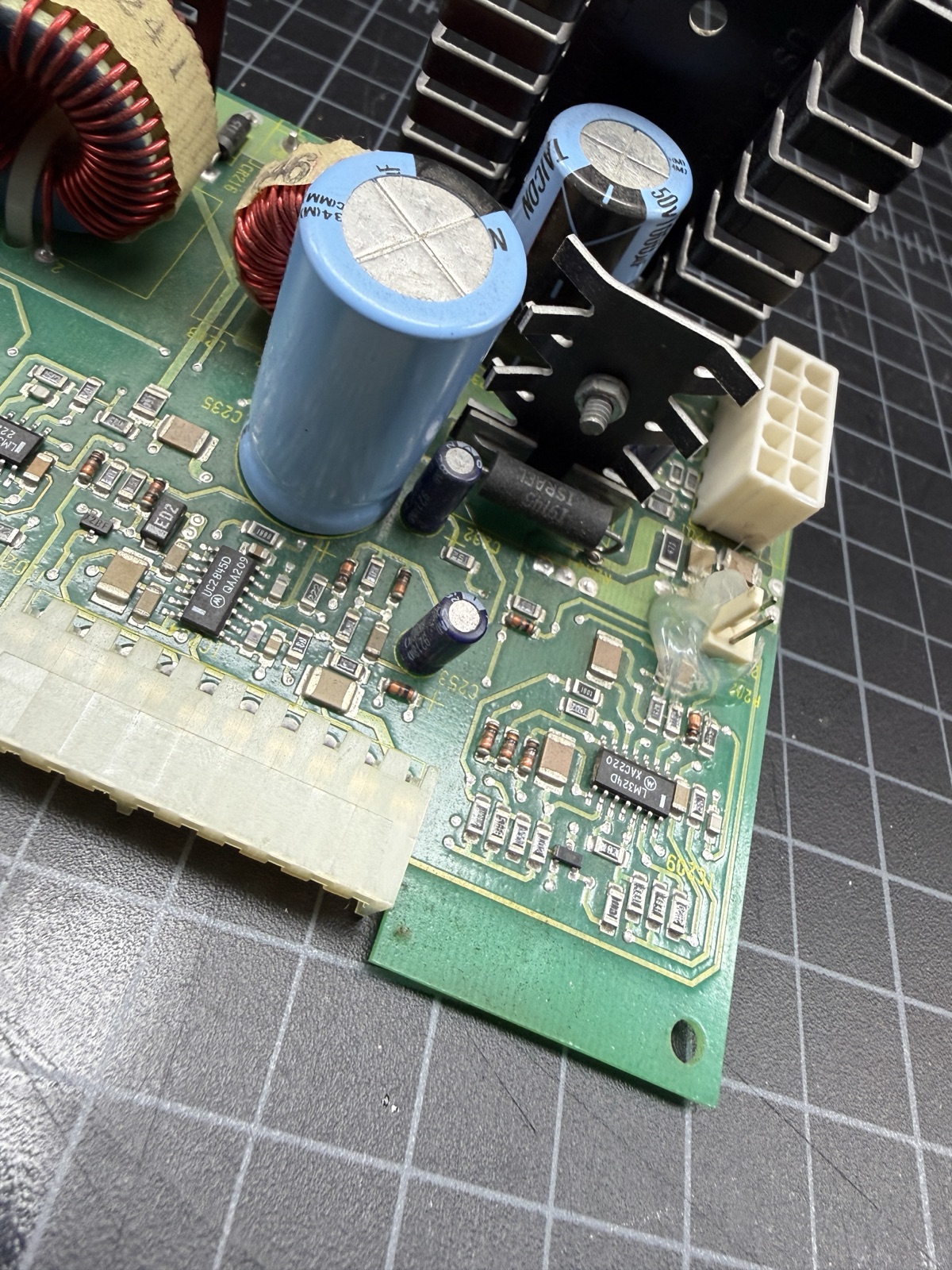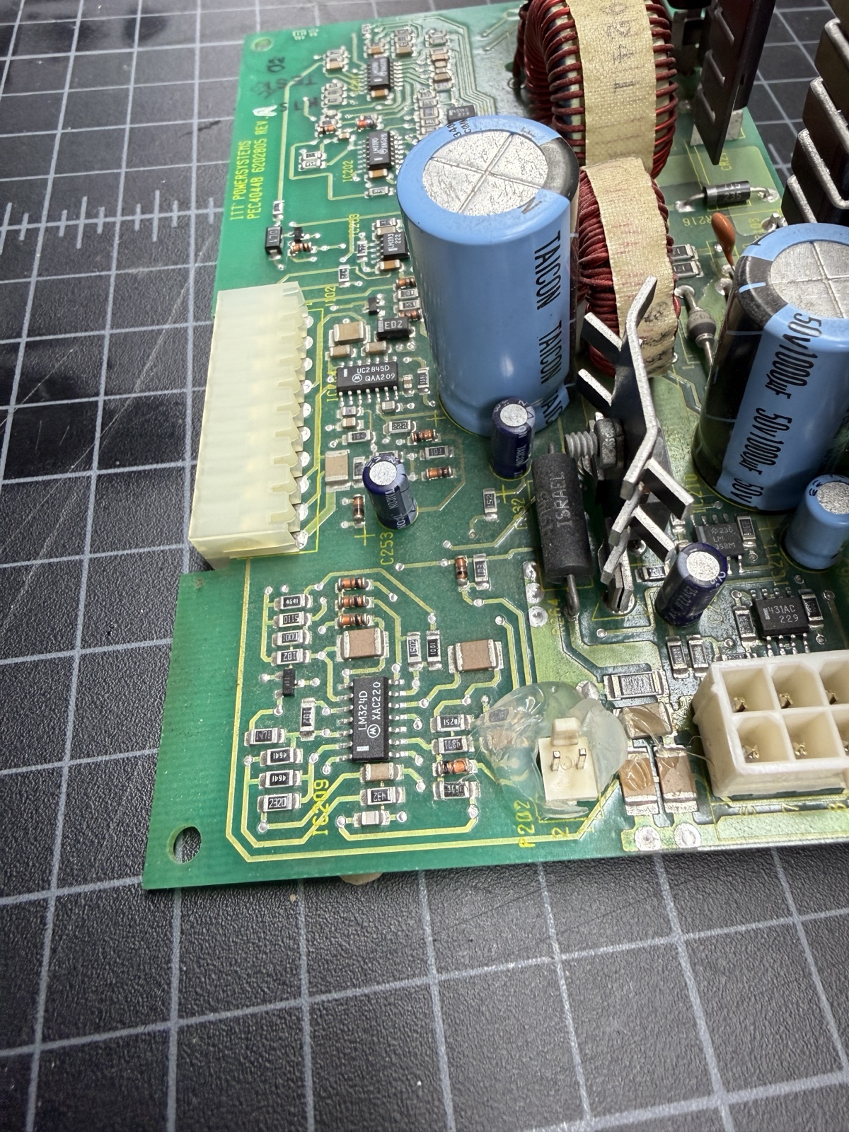
My Indigo R4400 is the prize of the collection, and it died a few months back. I had started it to do some work and it booted up fine. I left for about an hour, and when I came back it was dead. A power cycle did nothing except a single click from the speaker, and the LED on the main board never lit, which pointed to at least the 5V rail not being energized.
I had faced this problem before with my Indigo R3000. I did a lot of legwork trying to fix that supply, but in the end there just wasn’t much information on the internet about it, and certainly no schematics. That machine ended up with a new supply constructed from three different donor supplies. It worked, but it was a hack that consumed nearly the entire power supply location plus most of the drive bays. Not elegant.
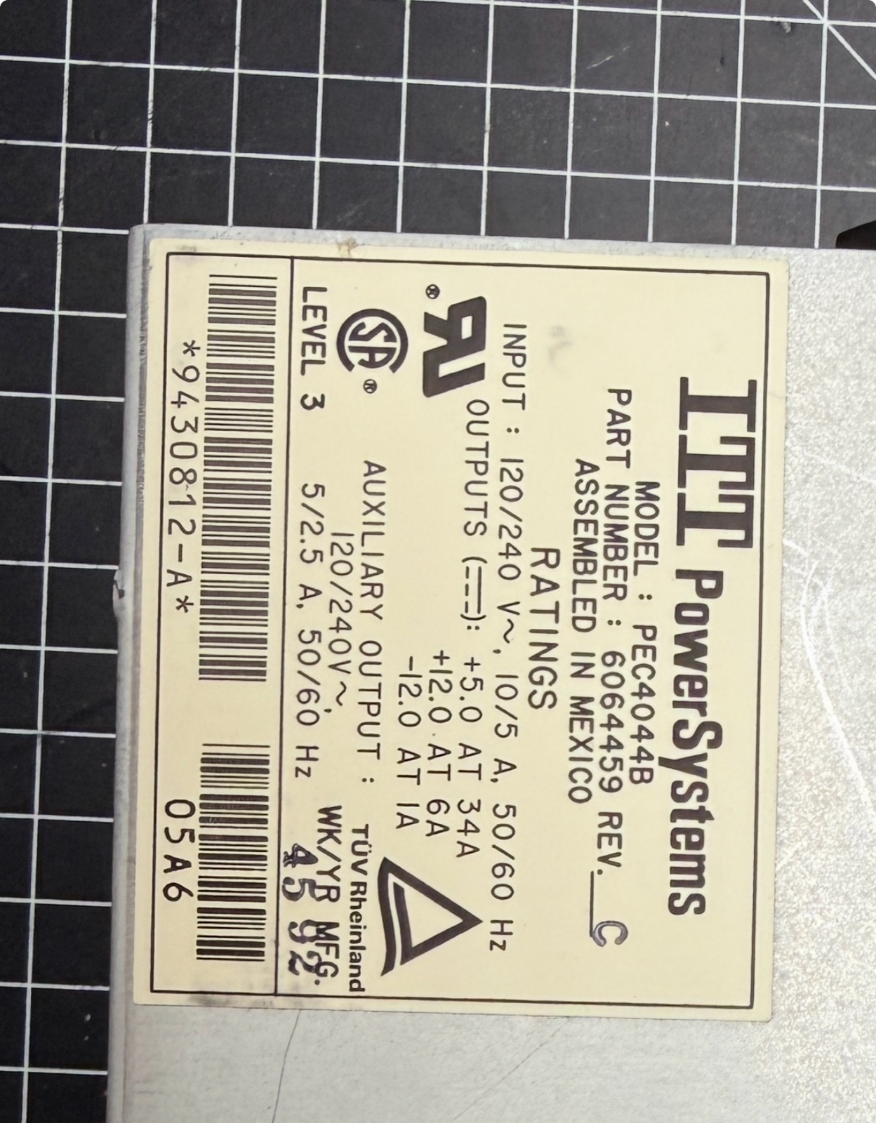
The supply is an ITT PowerSystems PEC4044B (part number 6064459; mine is a Rev C built in late 1992), and it is basically unobtainable. You never see the supply for sale by itself, and if you did it would probably be broken. None of the usual SGI parts sources carry them.
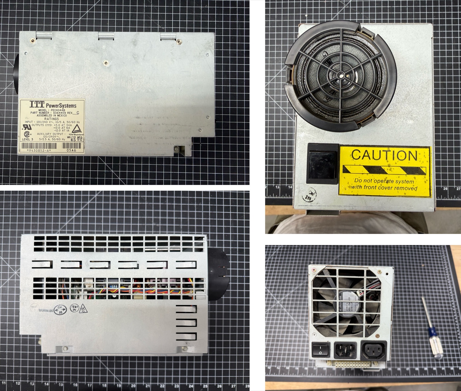
There is a commercial fallback, the Power One PFC375-4000F, an industrial supply that has been grafted into older SGI gear, but they’re expensive and it’s another fill-the-drive-bay solution.
This time the plan was to repair it properly, which I assumed would be a complete recap. That often fixes old power supplies, but it’s also kind of a shotgun approach. I’m not great with analog electronics and I generally hate working on power supplies. I really don’t have a natural intuition about them, especially ones without schematics.
But this time I was a little more emboldened to try, because I’ve been using AI so much (Claude to be specific) that I thought it might be my X factor with this effort. Plus I just wasn’t going to let this computer fall by the wayside.
The PEC4044B is essentially undocumented. What exists online is a handful of forum threads from a few determined owners; really only about four attempts are documented, and they were not all successful. Like a lot of PSU fixes, in the end the owner doesn’t always really know exactly what fixed it.
Some useful threads on this are:
JeffC’s thread on IRIXnet, and Elf’s “Indigo 1 Power Supply Basics” on the Silicon Graphics User Group forums, which is the best source I found on how this supply behaves.
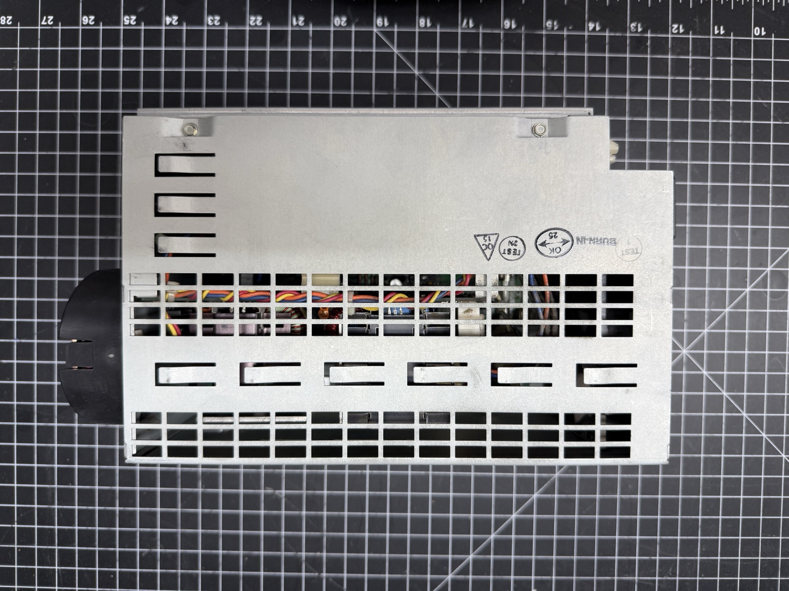
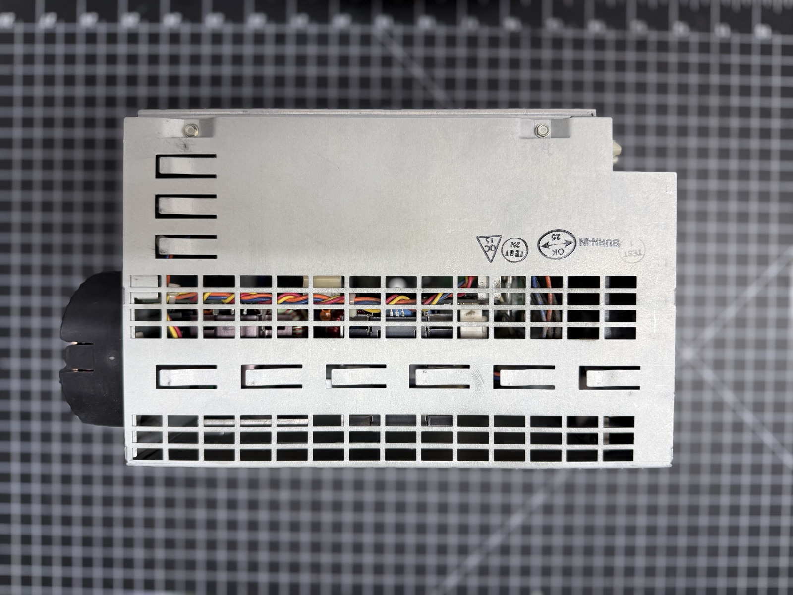
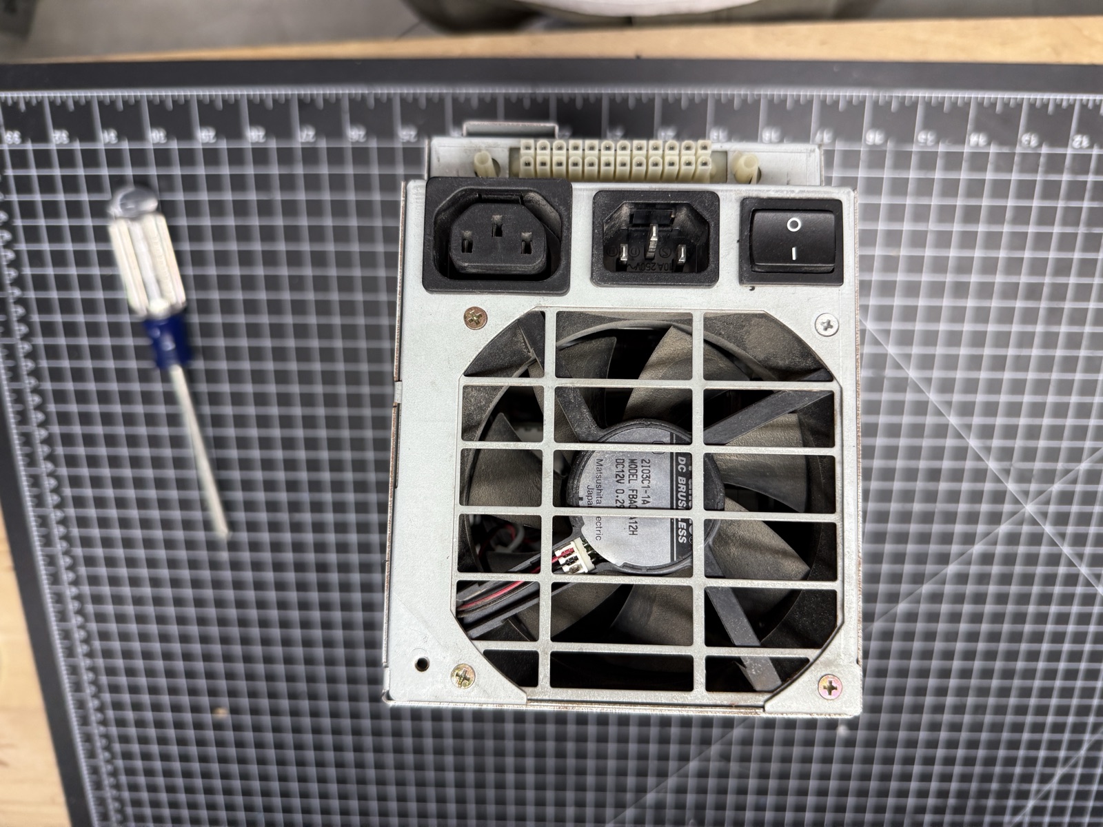
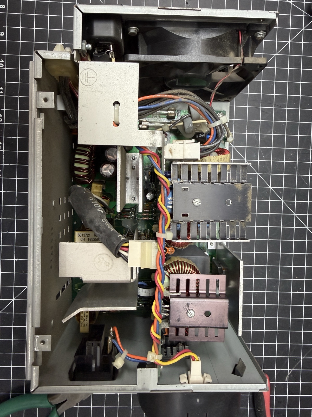
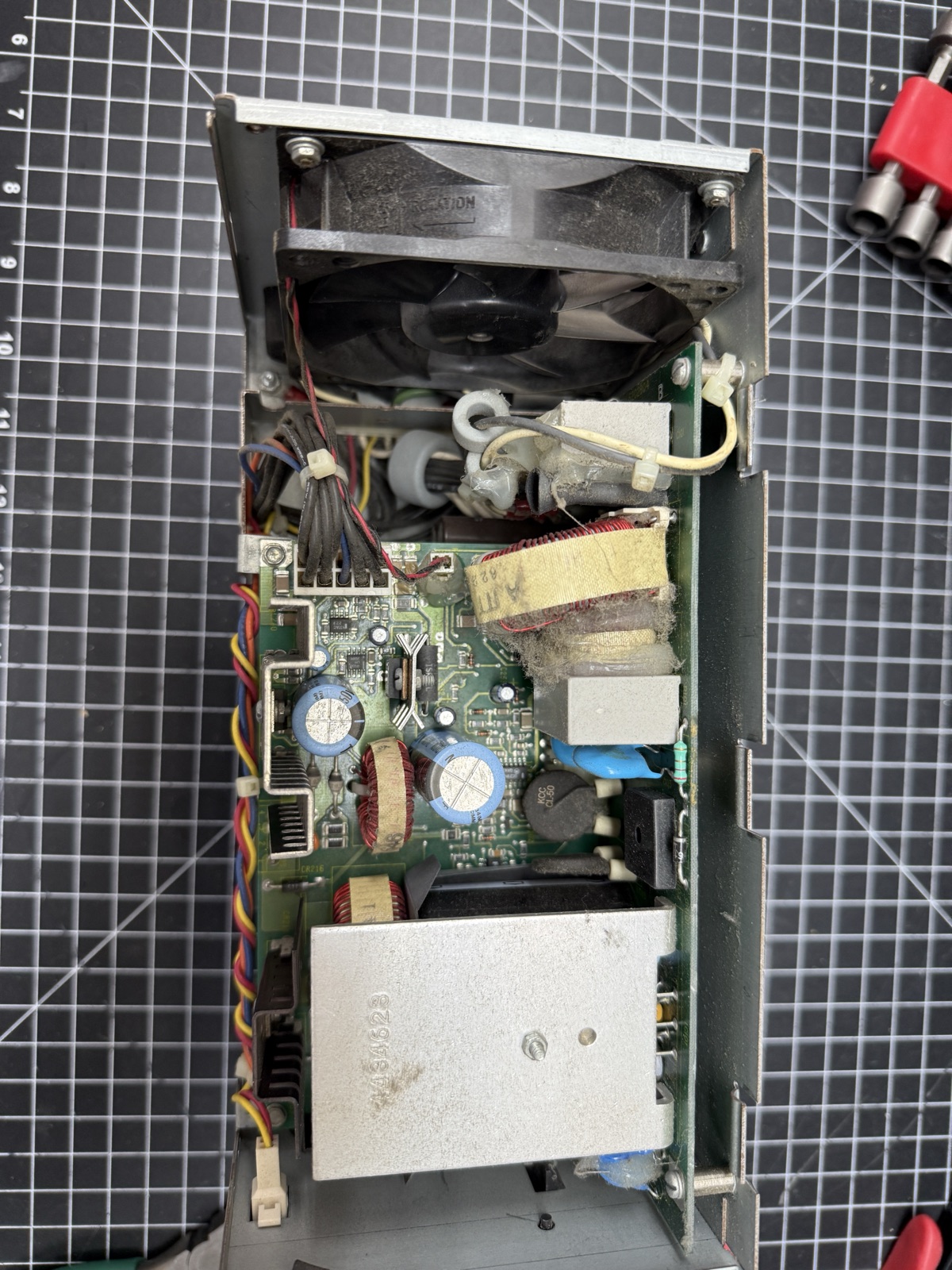
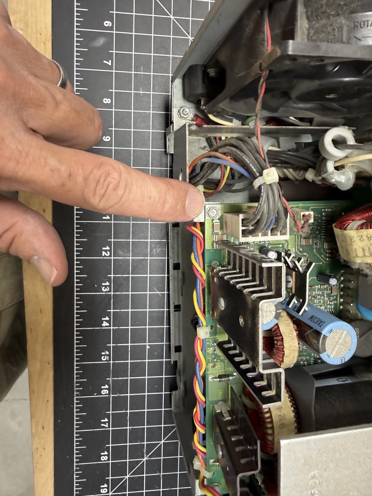
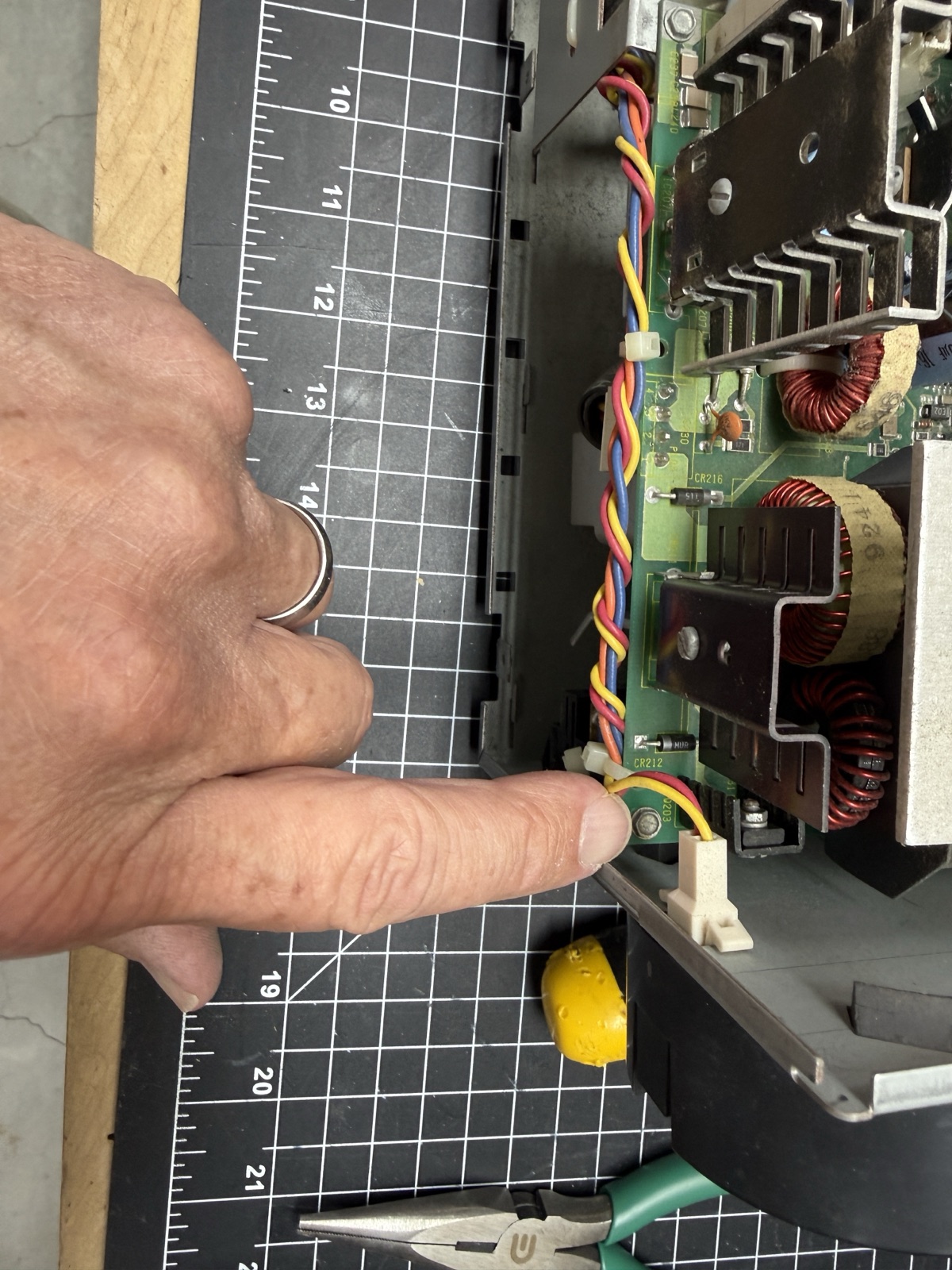
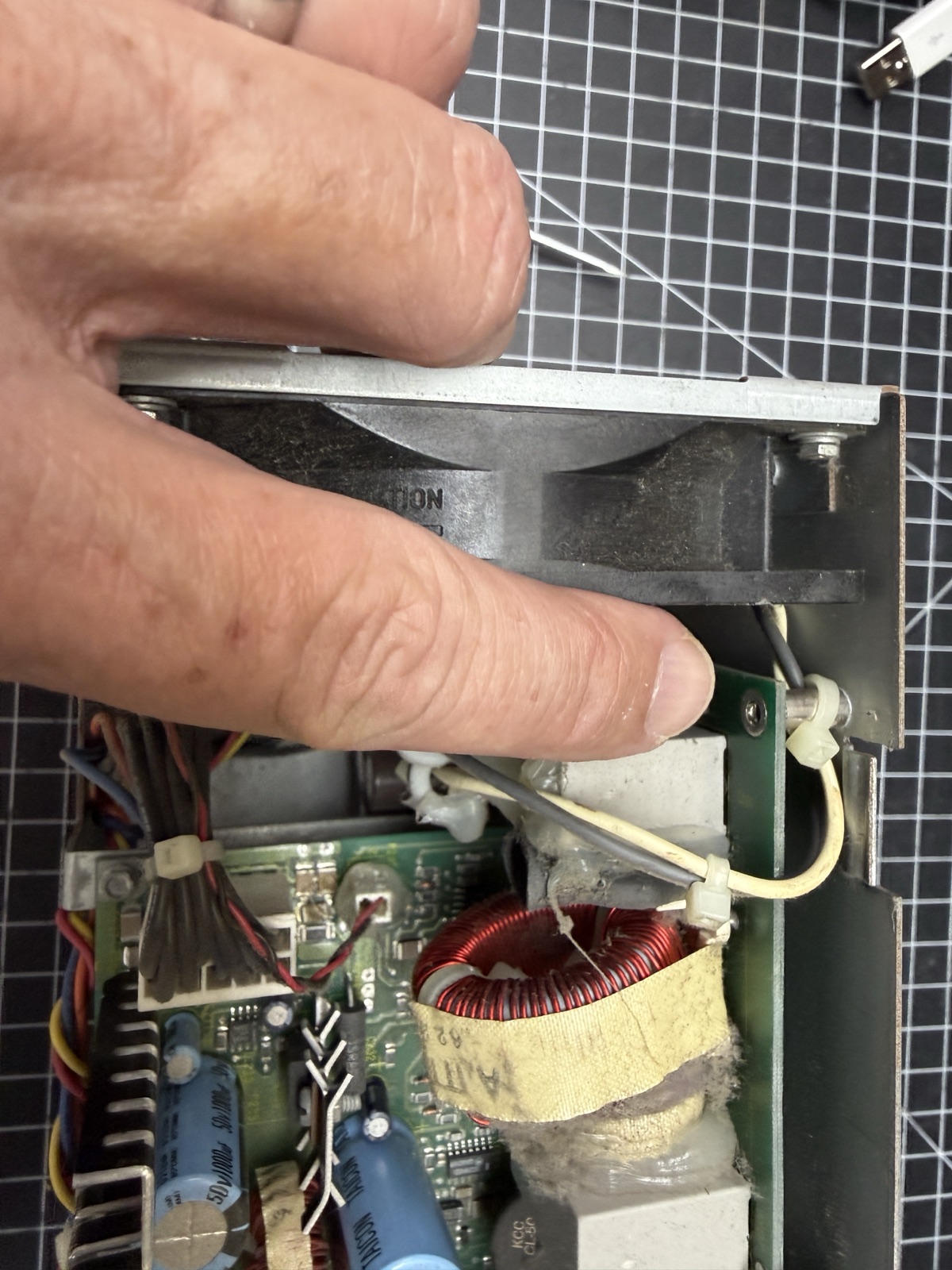
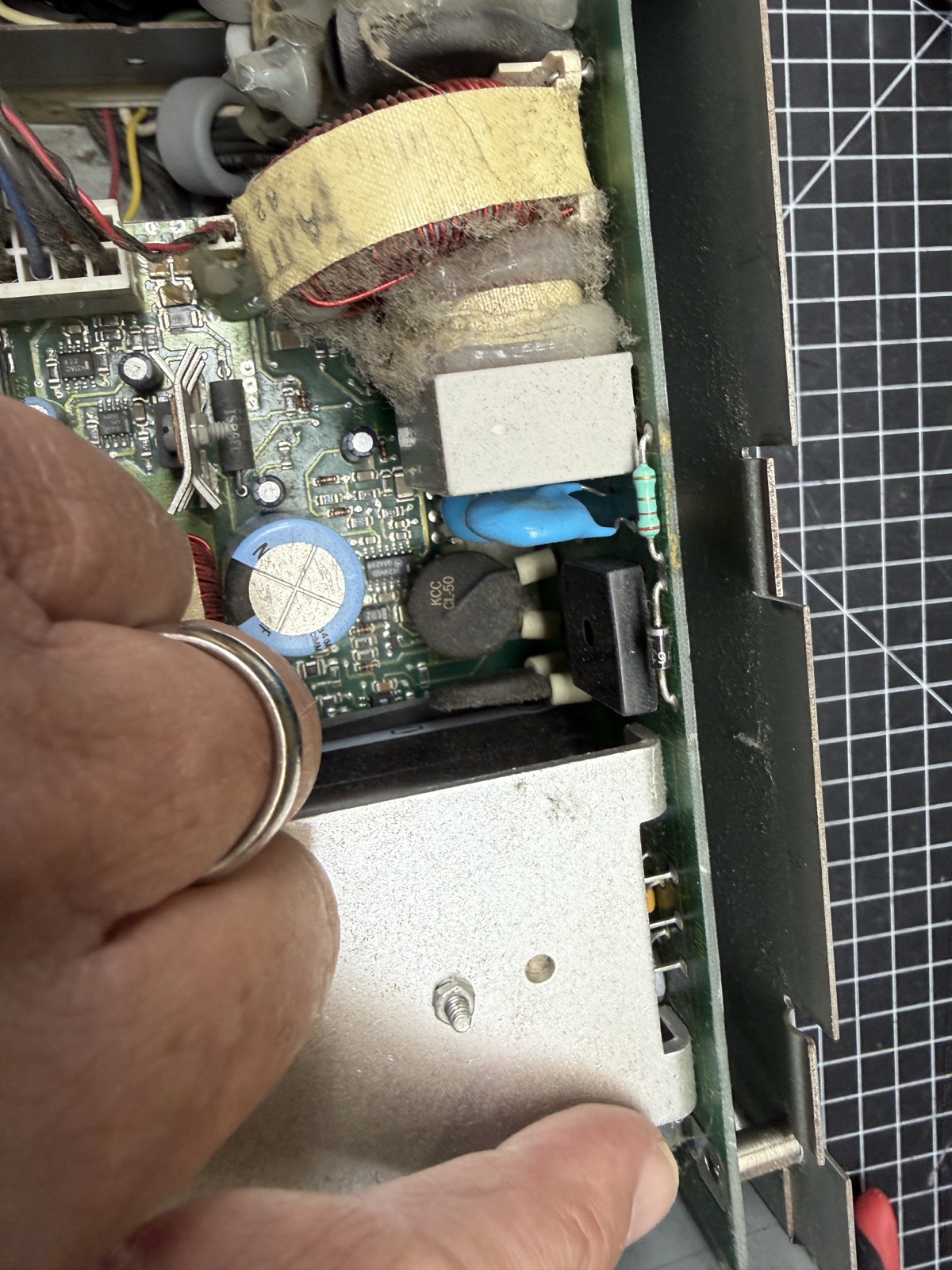
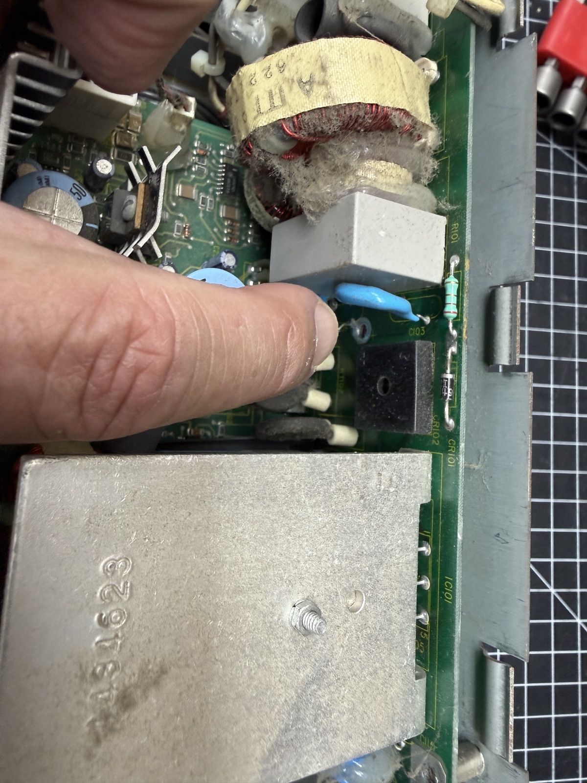
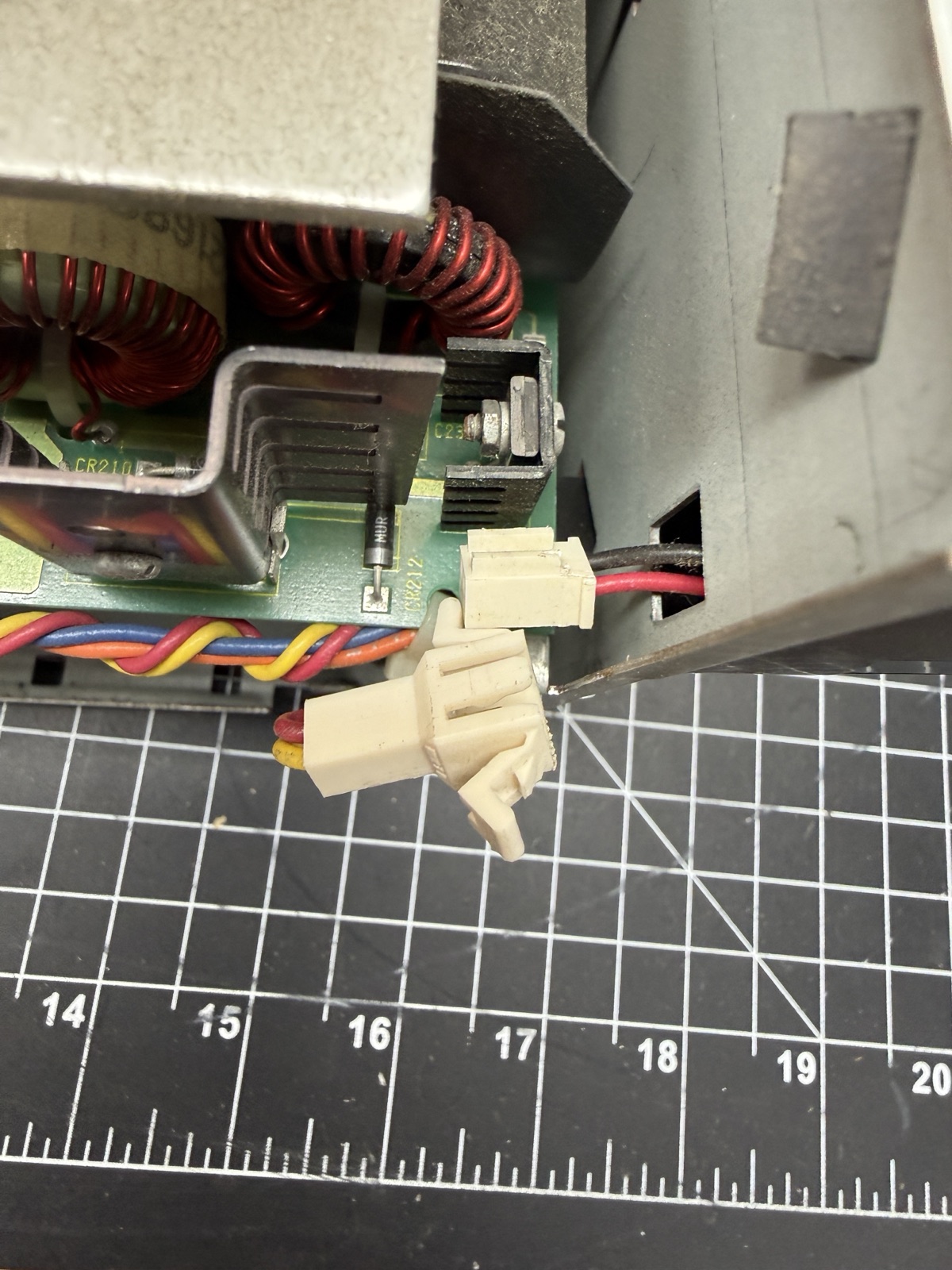
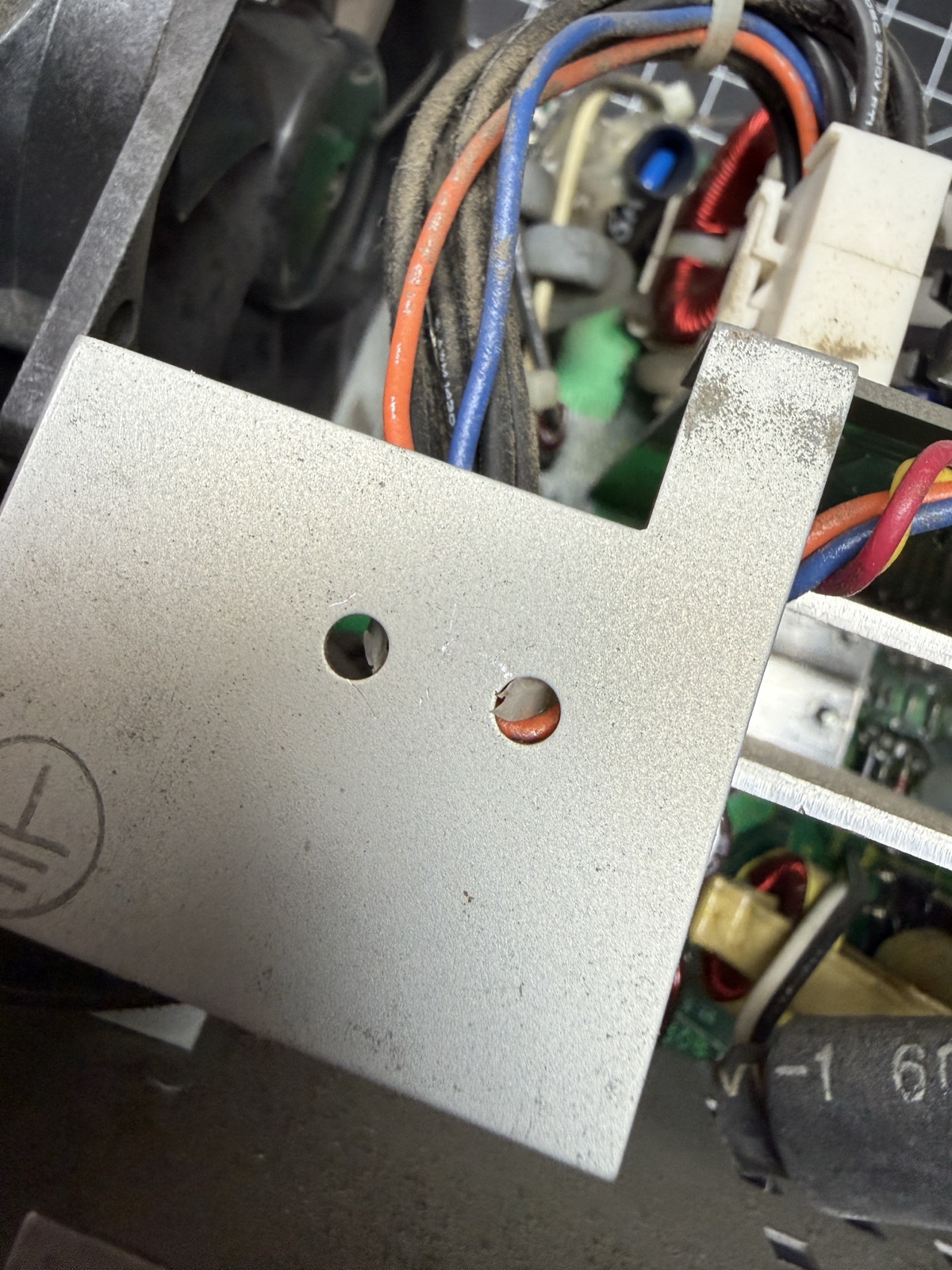
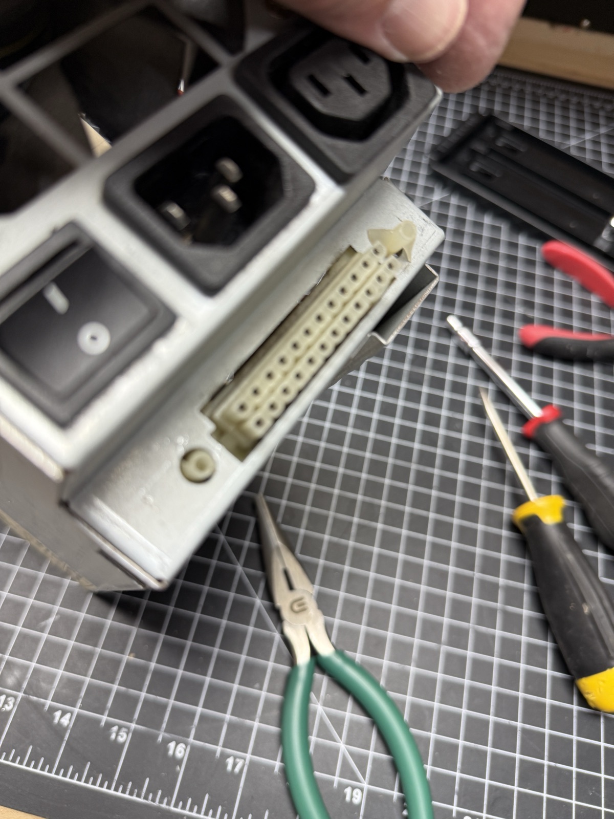
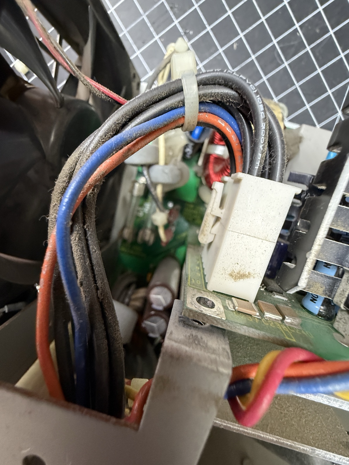
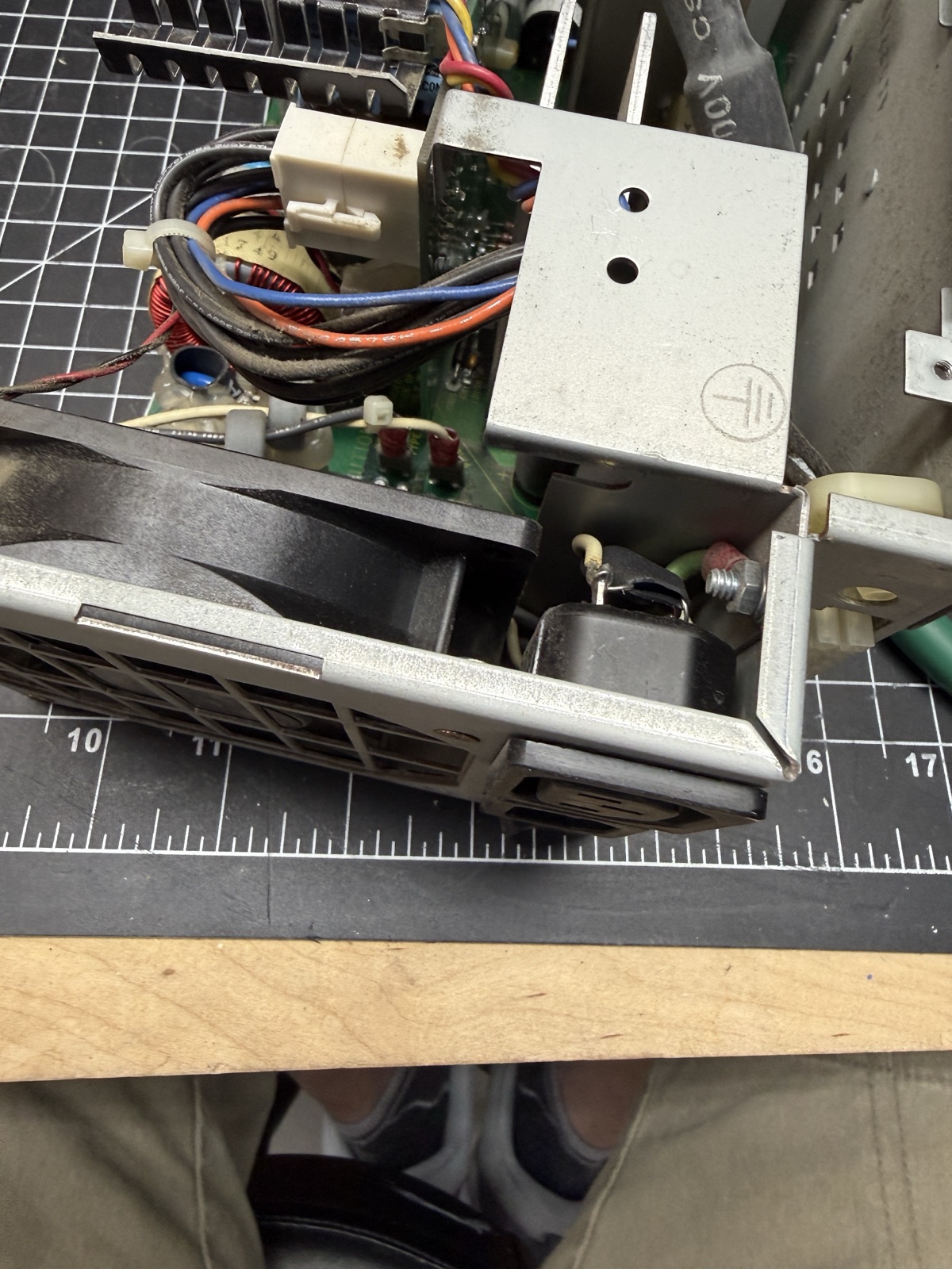
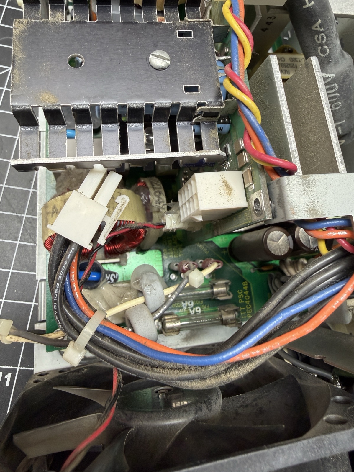
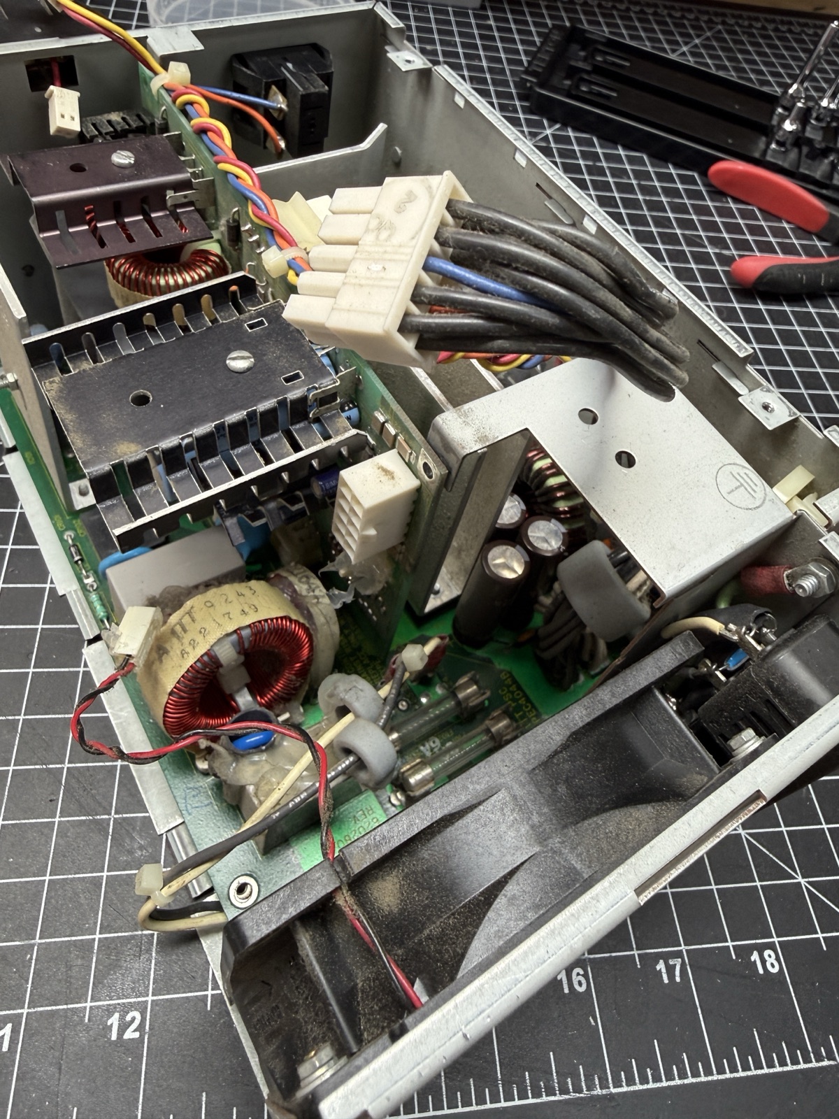
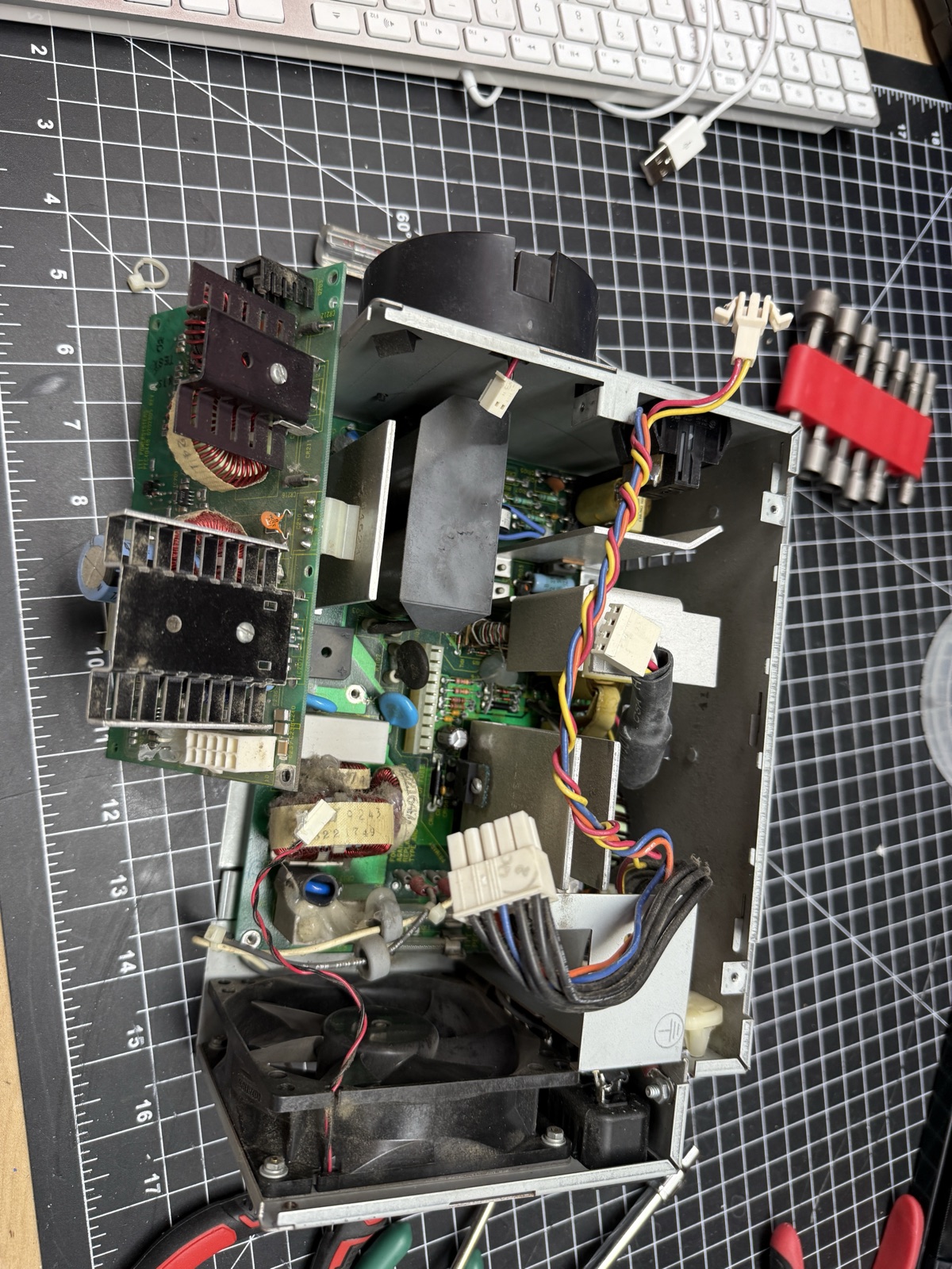
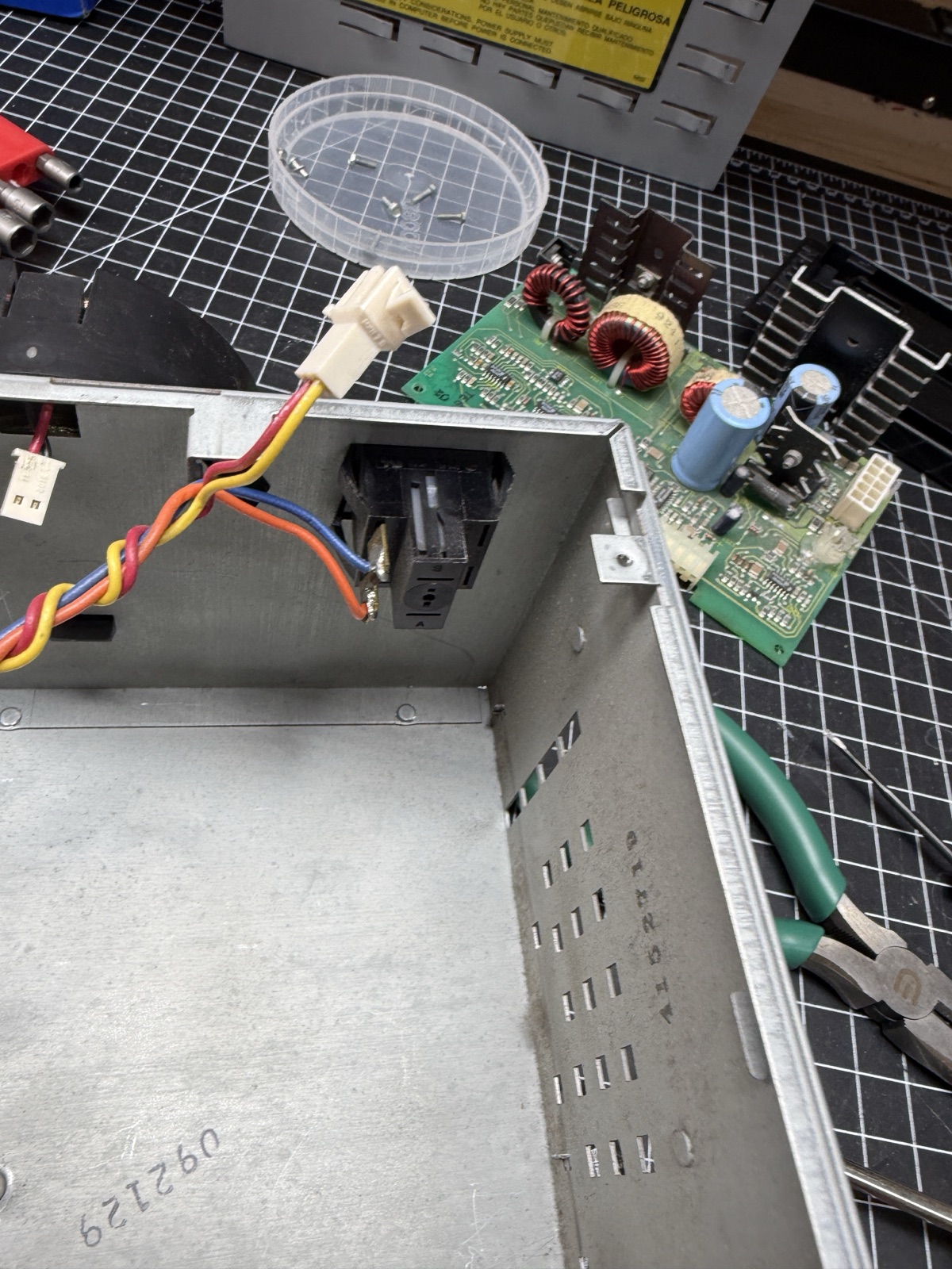
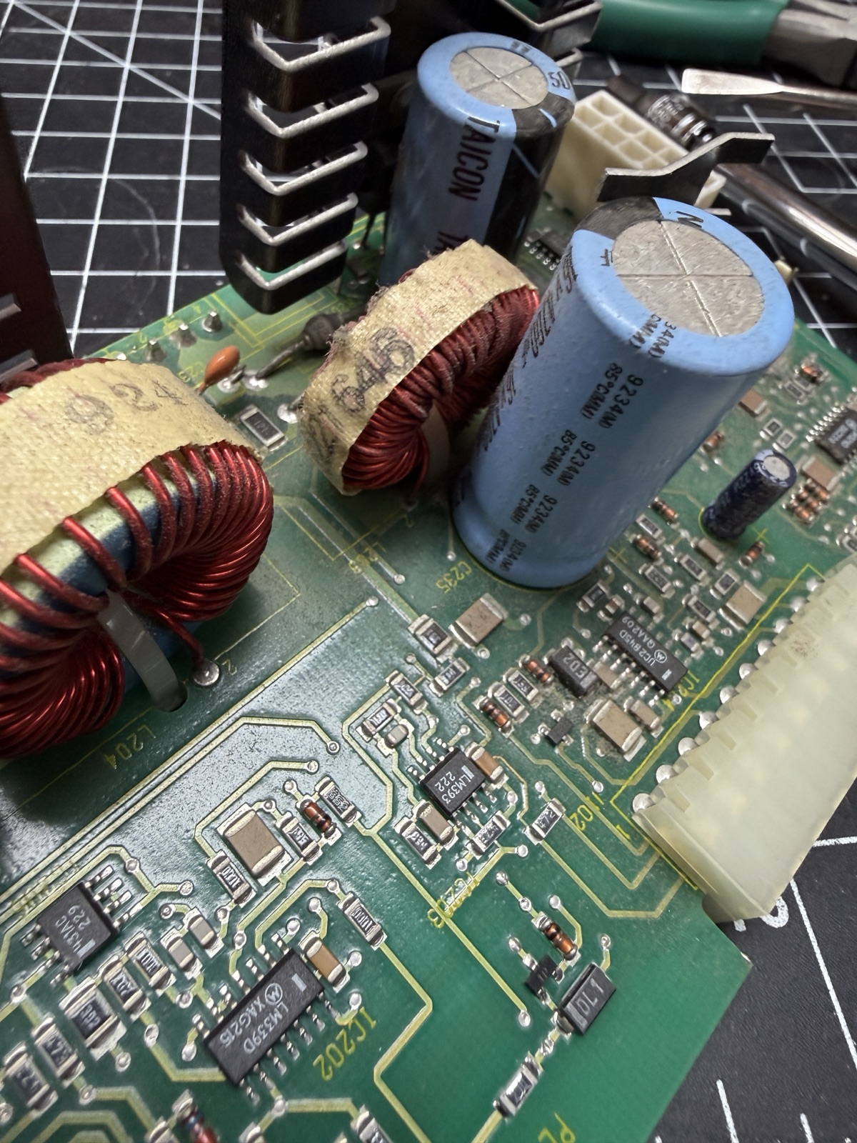
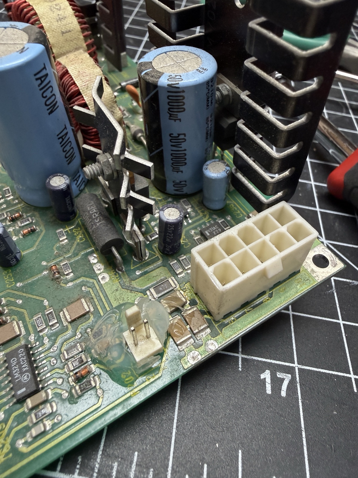
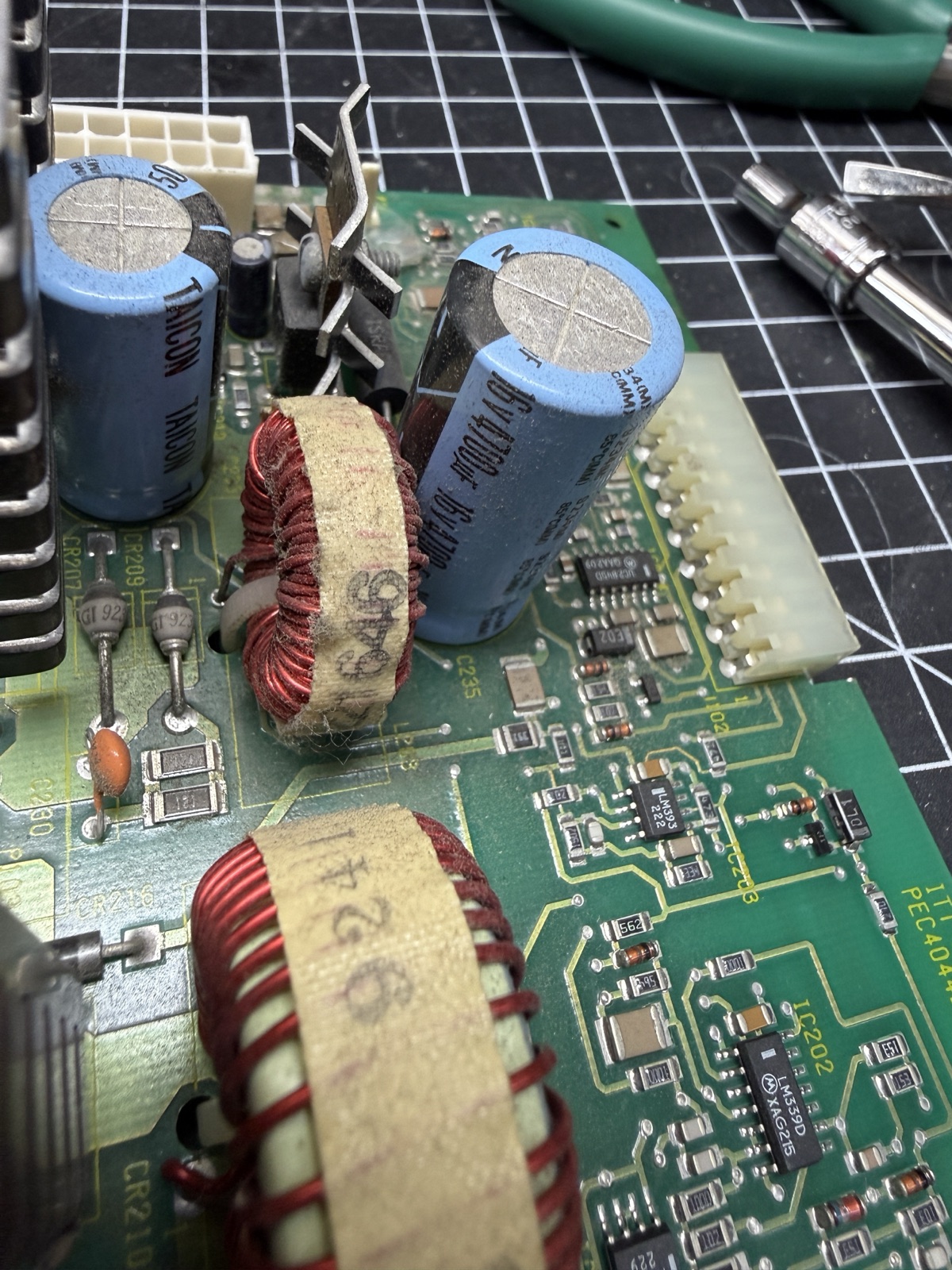
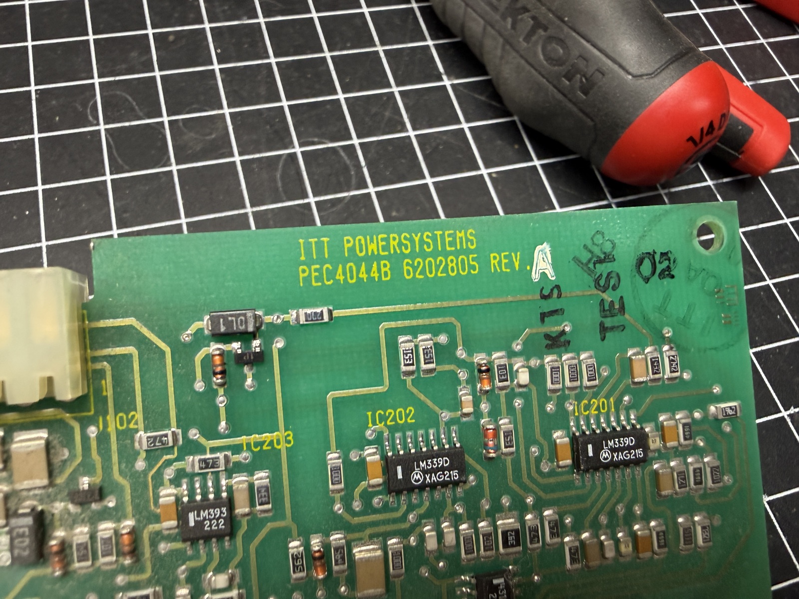
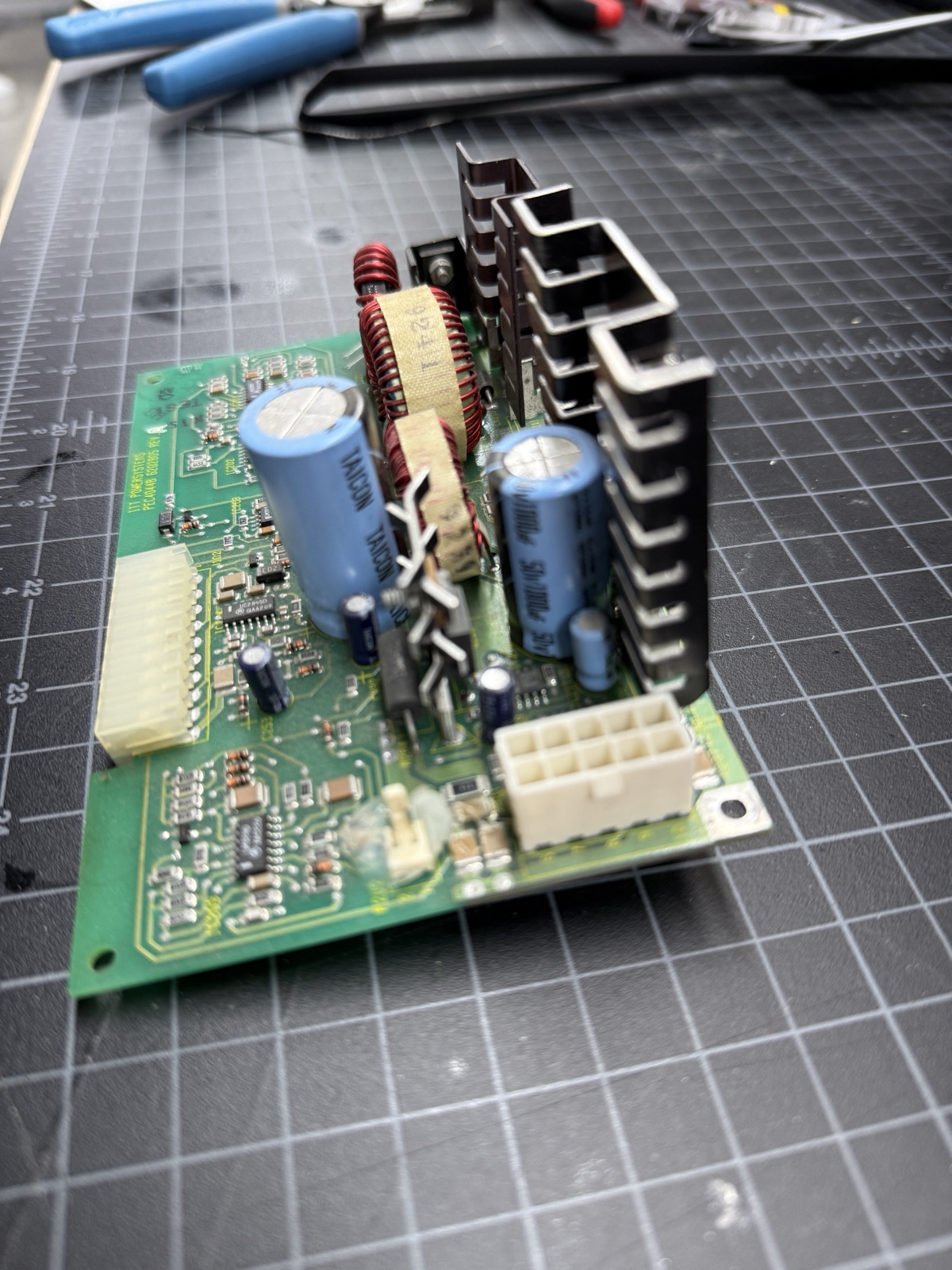
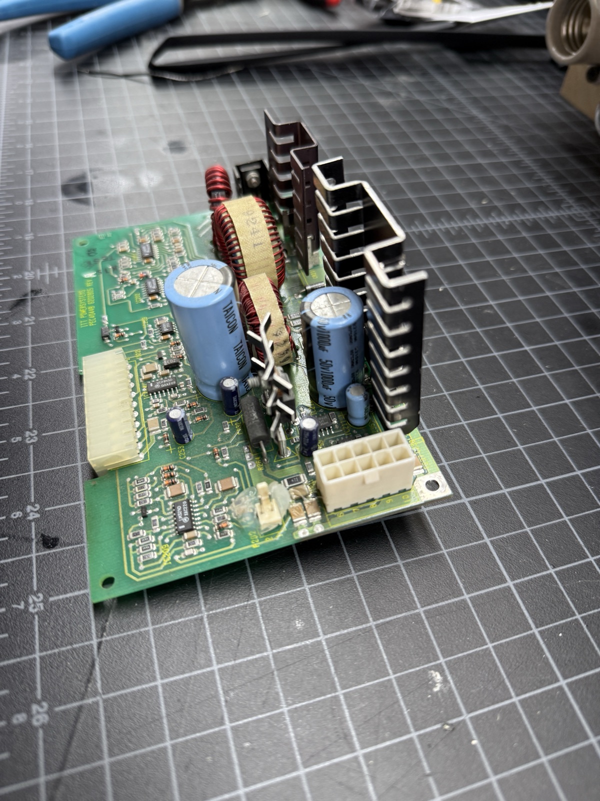
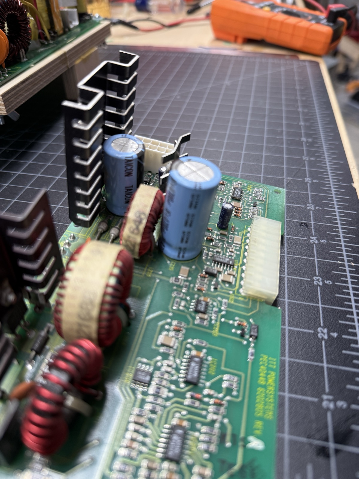
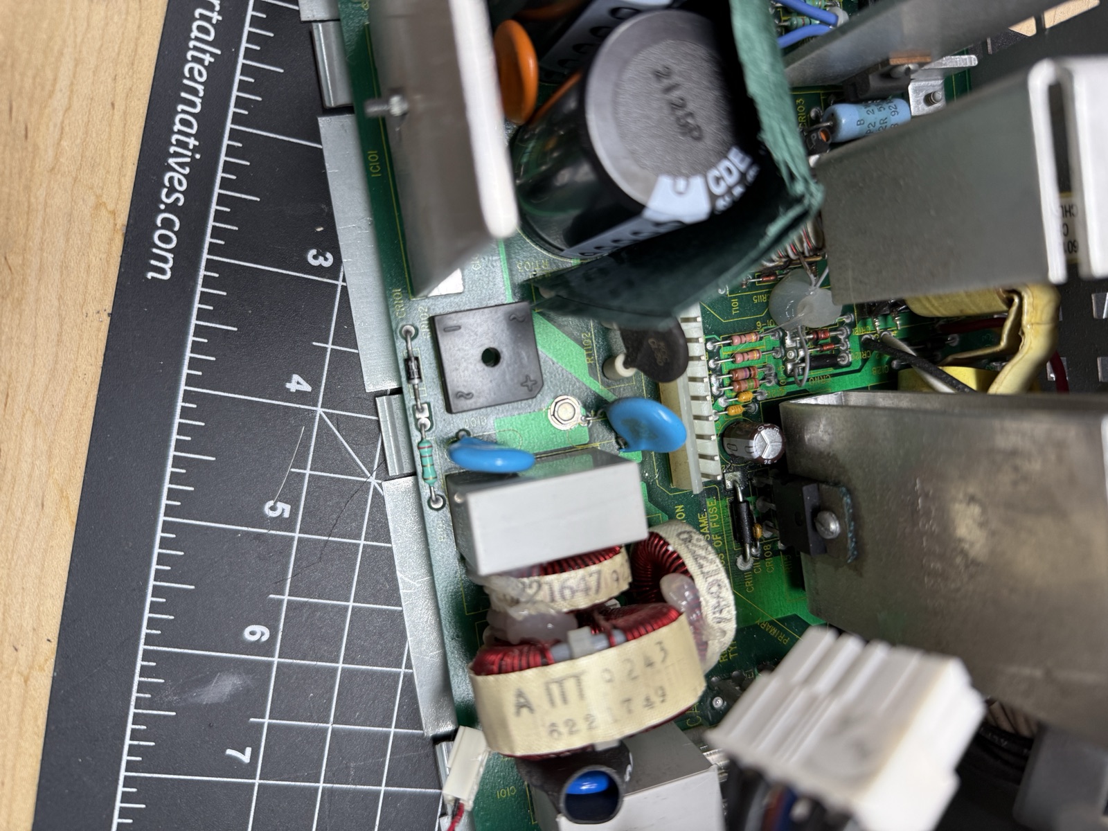
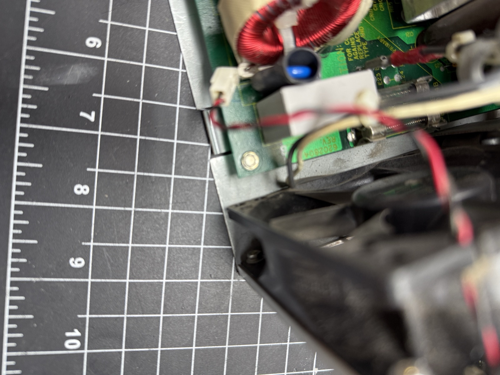
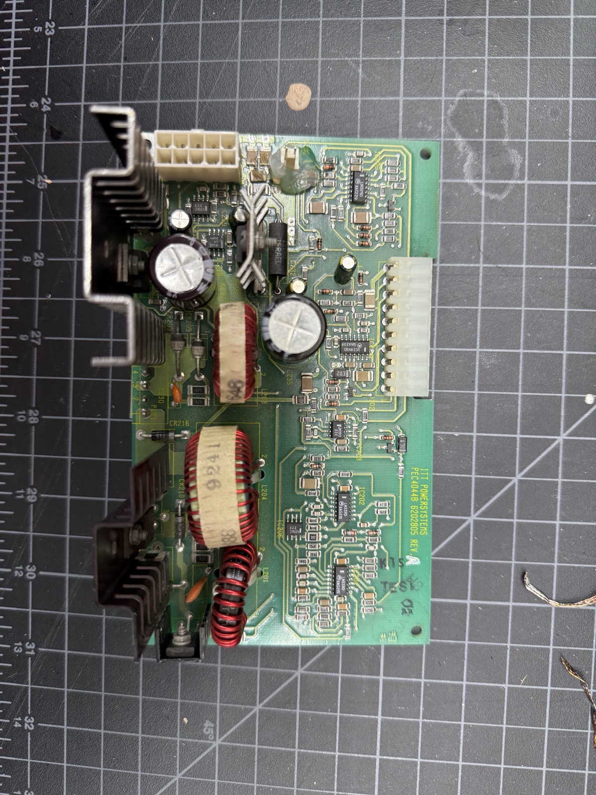
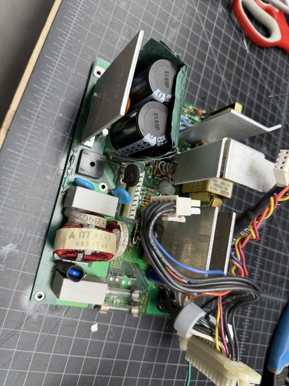
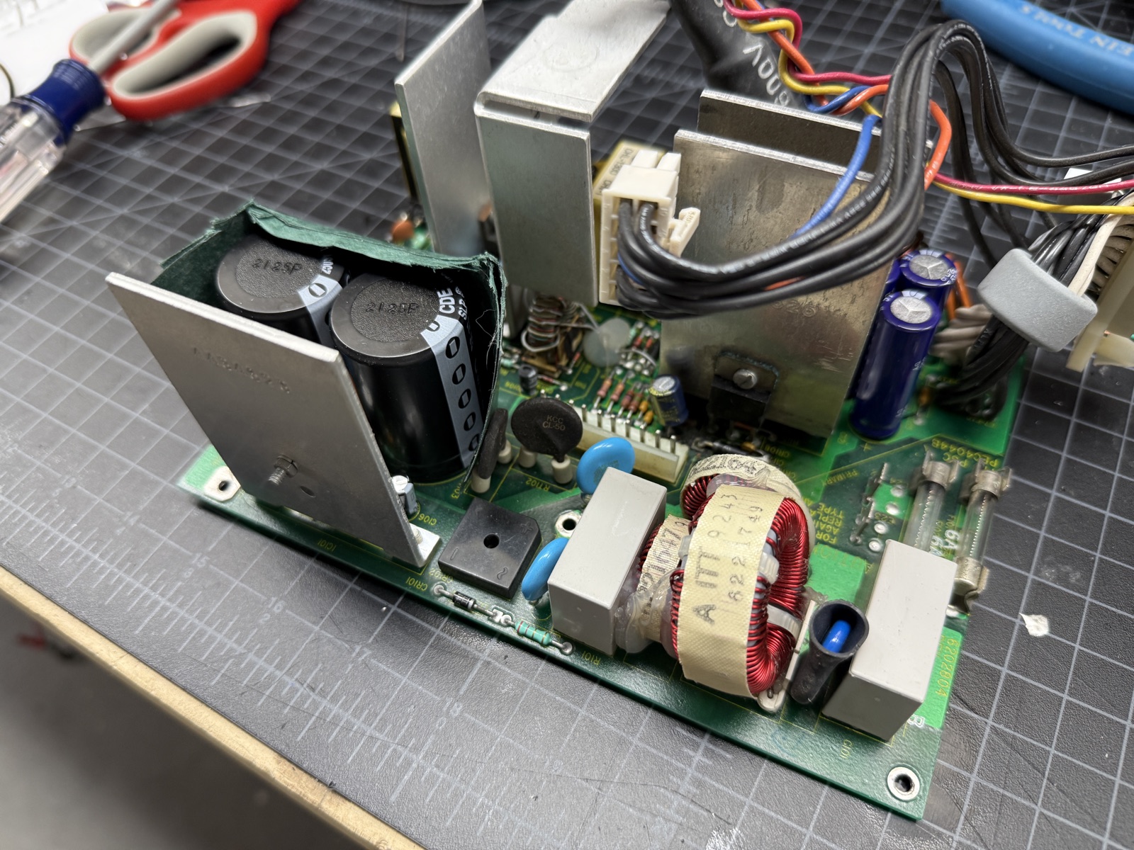
The supply is remarkably small for something that delivers 34 amps at +5V (per the label), which is what makes it nearly impossible to substitute: nothing modern in this form factor comes close on the 5V rail. Inside, it is two boards: the main power board, and a control board that plugs into an edge connector at a right angle, tied to the main board by two heavy wire bundles. That is about the extent of the documented anatomy; everything else here had to be worked out on the bench.
How it failed
I’ve had this machine in my collection for maybe three years. I bought it from a fellow collector and friend. It worked when I got it, and I have run it off and on ever since, sometimes for as much as a few weeks and sometimes only a day.
It had been off for some time, and when I started it up a few months back I left it for an hour or so, and when I came back it was dead. The power switch did nothing.
Honestly, I have been a little hesitant to use it, as it’s one of my favorites and I was afraid of this exact scenario.
There were warning signs, and in hindsight they were all the same problem. The R4400 write-up on this site records me noticing faint noise on the screen and musing about a proactive recap. The machine also made a half-second scratchy sound from the speaker at every startup, for years. Both were symptoms of failing power, and both are gone now.
Be careful!
Some of this is mains-side work (AC from the wall). A switching supply stores a potentially lethal charge in its bulk capacitors, and unplugged does not mean the PSU is safe. The big pair in this supply (C108 and C109) sits at around 300V combined and can hold it long after the cord comes out. In practice I found that mine generally discharged on their own pretty quickly (around 30 seconds), so there is clearly something in the design to drain them, but don’t assume that circuit is working.
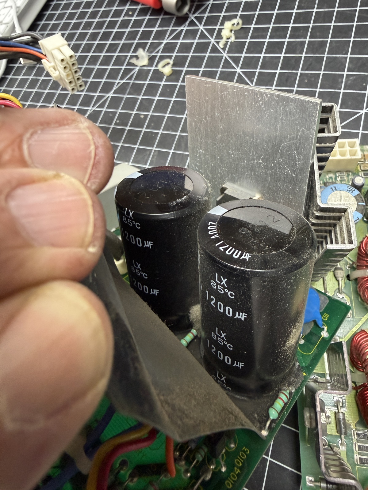
Before touching anything, every time: unplug, discharge the bulks (C108 and C109) through a 4.7kΩ 10W resistor on insulated clip leads, then verify with a meter that they’re down to a few volts or less.
If you use an oscilloscope (which was very helpful for this diagnosis), keep it on the isolated secondary side (it’s usually printed on the board); a grounded probe clip on the primary is a short circuit through your scope.
Use the correct tools; it’s not going to go well without them
I have a good soldering station, but it is not built for high-power work, and this board has heavy traces and big through-hole parts (all with bent leads, unfortunately). So I bought a Weller W100PG, the classic 100 watt spade-tip iron with a CT6F7 700°F tip, apparently a fixture on power supply benches for decades, according to Claude. A big fat iron is ironically safer than trying to limp along with the wrong iron or a non-chisel tip. You will likely do more harm with the wrong iron than with the correct one running at a hotter temp.
For testing the parts that came off the board I added a Peak Atlas ESR70, a highly rated capacitance and ESR meter. Cheaper ones use DC to measure the cap, and it’s a little sketchy how well they work. A better one uses AC and measures almost instantly.
You are going to need to build a test setup. There is no working on this supply in the actual computer, and you probably shouldn’t even if you could. It’s hard to hold a board, a soldering iron, and pliers all at the same time. Don’t even try it.
The test jig
I bench-ran the supply outside the machine, because you really have no other choice.
Having messed with one of these before, I knew how difficult this supply is to work on; everything about it is compact. So in my workshop I built a wood jig that mounts the main supply board and lets me turn the whole assembly around to get at its different sides. One of the harder things about working on a PSU is that you kind of need three hands, and the jig takes the place of one of them, or at least half a hand.
I added three light bulb sockets to the base: one that the incoming AC runs through, one for +5V, and one for +12V. Supplies generally need some kind of load (demand) on them to function correctly, and some (like this one) will shut themselves down without one, feigning their own death.
The jig’s electrical parts were as follows:
A series ballast on the AC input. I used a 250W heat lamp after it turned out that a 100W bulb starves this supply (more below).
A dummy load of automotive 1156 bulbs on +5 and +12, wired into the output connector with 18AWG solid core. That gauge fits this connector well. It seats snugly in the pins (20AWG is too loose), and short lengths of it made good test points for jumpering and probing signals like Soft Start and the pin 12 status output.
A Tektronix TBS1052B scope on the outputs. Not technically required, but without it this repair would have been more of a guess.
Most of this is the standard stuff from my article Bench Tools for Vintage Computer Repair; the 1156 bulbs and the heat lamp were improvised for this job, but both were Claude’s suggestions.
Here is how it all wires together:
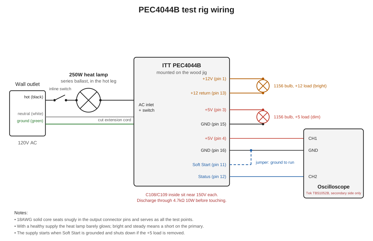
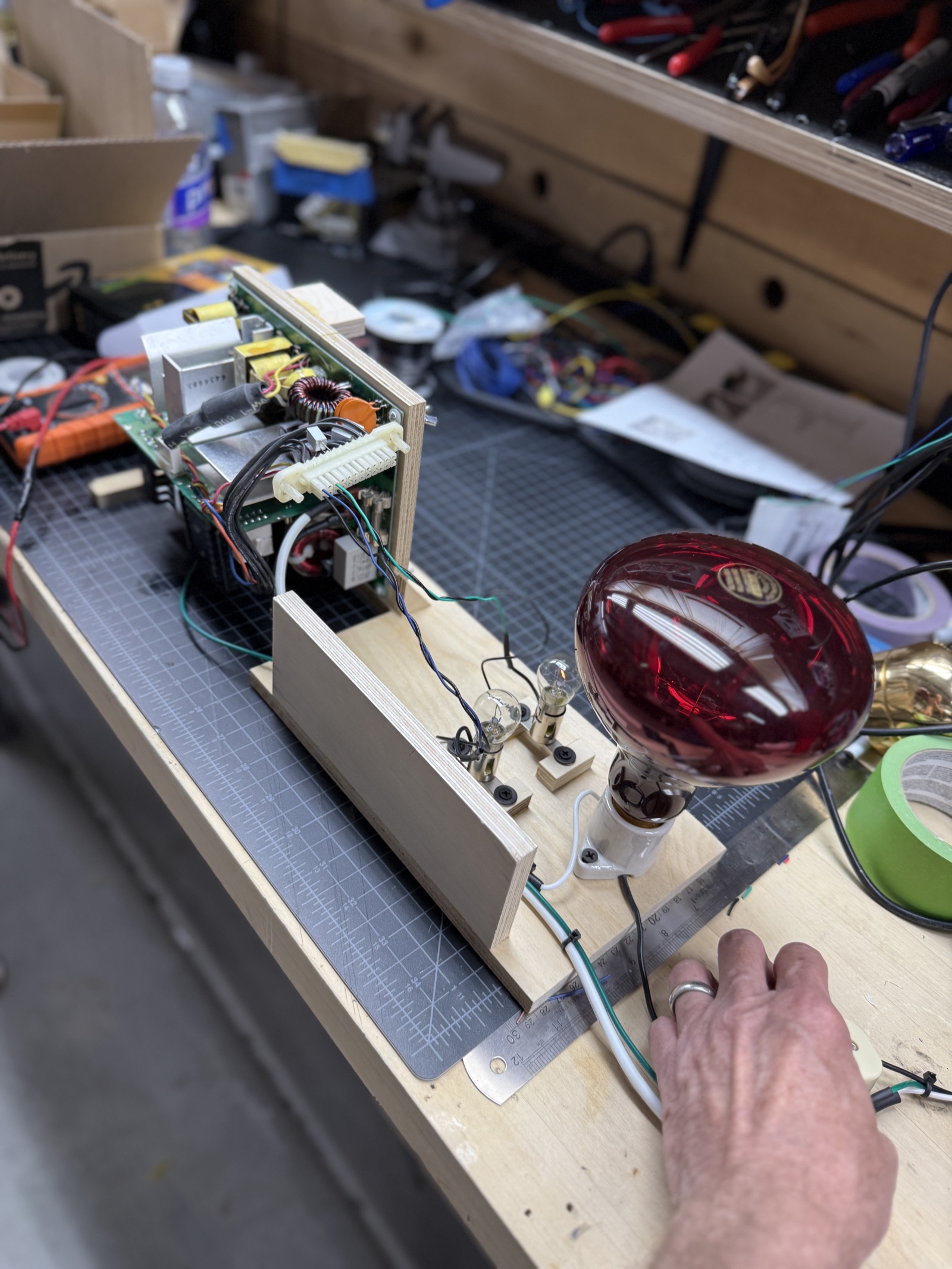
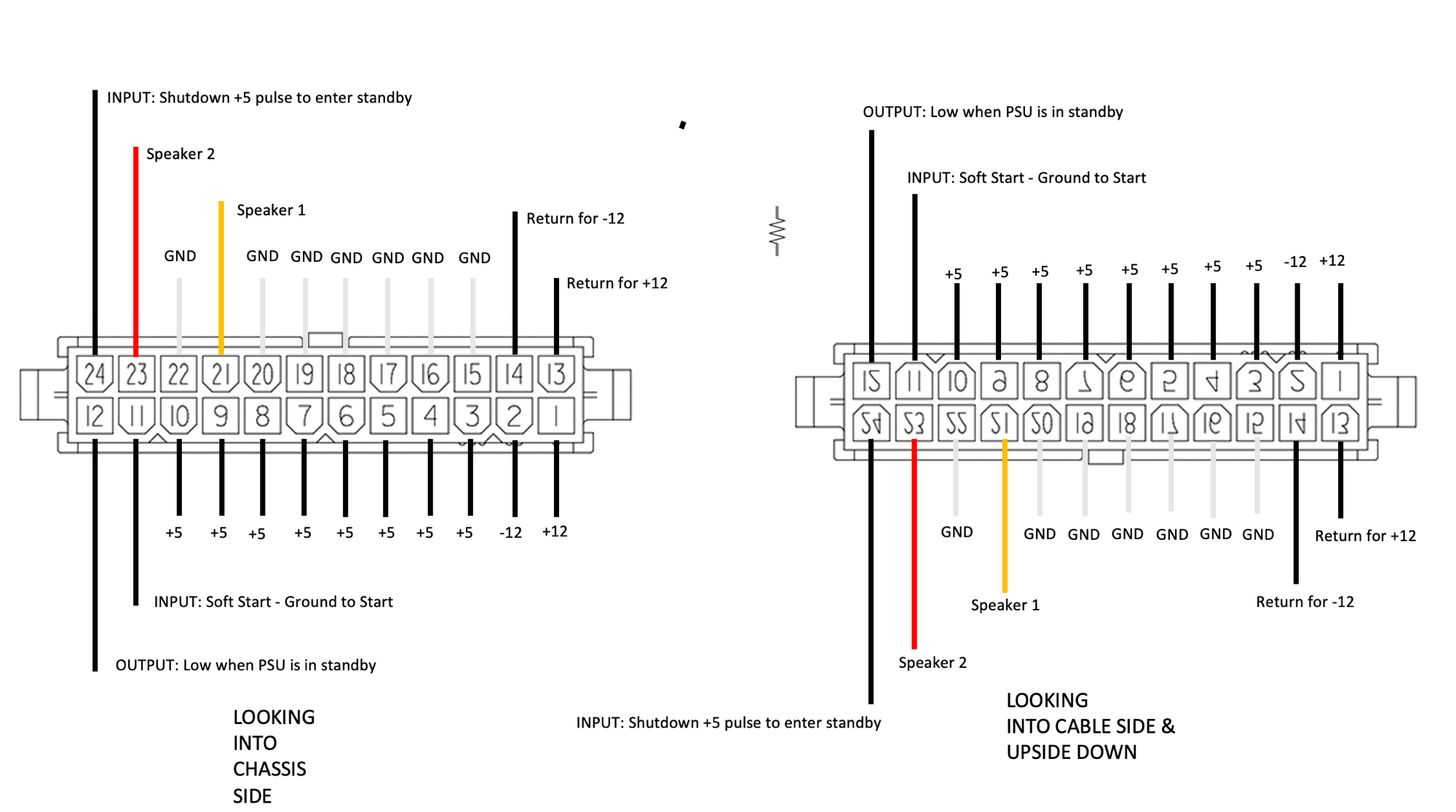
The jig I built from plywood ended up holding the output connector upside down. I had a pinout from the R3000 franken-supply work, drawn looking into the chassis side, but on the bench I was facing the opposite connector, flipped upside down. Rather than re-derive every probe placement in my head and eventually get one wrong, I drew the second view and kept it on the bench. Both views are below.
What’s the heat lamp ballast all about?
The heat lamp is a dim-bulb tester scaled up to match the supply size. A series incandescent ballast limits fault current: a hard short on the supply primary lights the bulb up bright and keeps it there, so a mistake produces a bright bulb instead of burned parts. But the ballast has to be sized to the load. A standard 100W bulb in series with a roughly 300W supply drops so much voltage that the supply browns out.
A 250W infrared heat lamp is just a big incandescent filament, with the same protective behavior but enough headroom that the supply saw full line (150V and 156V across C108 and C109, verified) while keeping the short-circuit protection. In practice, with a healthy supply, the infrared bulb doesn’t really even light up, though you can feel some heat coming off it.
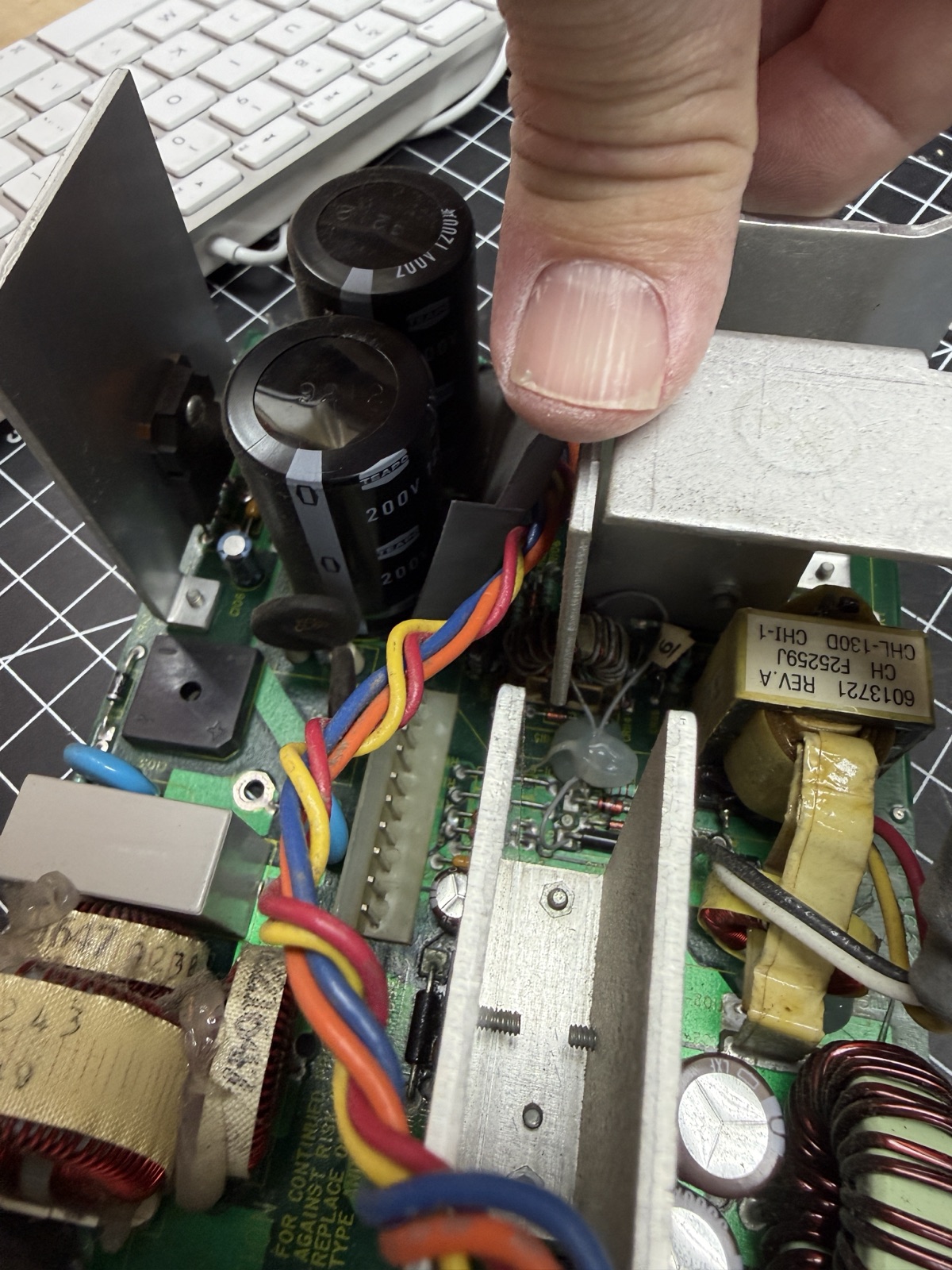
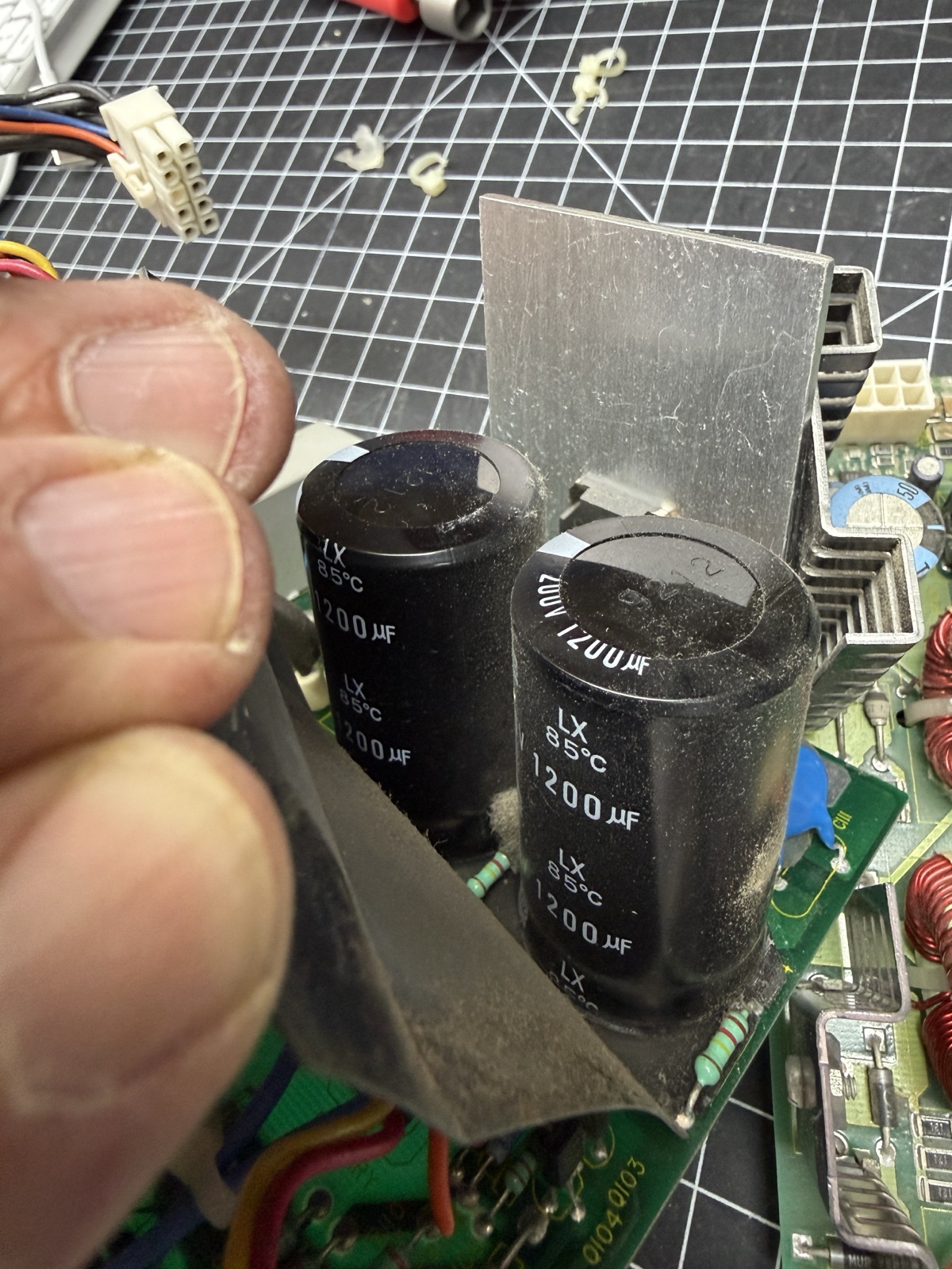
The bulk caps, C108 and C109, are the two big primary-side reservoirs that store rectified line voltage, and on this supply the pair (two 200V parts) sits in series as a voltage-doubler input, a common trick for running a big supply from a 120V outlet (I was told by Claude). So roughly 300V across the two, a bit over 150V on each cap, is what full line should look like. It’s also why the safety warning above is in here, and one reason for the wood jig.
A great first test once you get it all wired up is the voltage across each of those big caps; they should be really close to 150V each when everything is powered on.
The lamps also carry useful information on their own. On the ballast side, a brief flash at plug-in and then back to near-dark is normal inrush charging C108 and C109, no short. On the output side, the brake-light bulbs glow steadily in proportion to load. The bulb connected to +5V is a bit dim and the +12V bulb should be quite bright. This is normal behavior.
I never had a lot of heat coming from the heat lamp, so I knew there wasn’t a primary-side short in the supply.
The test rig shopping list
The complete rig, as actually used, sourced almost entirely outside of electronics suppliers.
Hardware store
- One 250W infrared heat lamp bulb: the series ballast, for the reasons above.
- One keyless lamp holder rated for the heat lamp’s wattage, about $4 with two screw terminals. Porcelain, not plastic, at 250W.
- One cheap three-prong extension cord you are willing to cut.
- Wire nuts or crimp connectors, electrical tape, and heat-shrink tubing to keep everything tight, together, and insulated.
Auto parts store
- 12V type 1156 bulbs (single-filament brake/backup bulbs) with pigtail sockets: the dummy loads for +5 and +12.
Electronics
- The replacement parts themselves (the full order is below).
- One 4.7kΩ 10W resistor on insulated clip leads: the cap discharge tool from the safety ritual above. Not optional.
- Alligator clip jumper leads.
- 18AWG solid-core wire for the output connector test leads.
How this supply actually works
Almost none of this is written down anywhere except Elf’s SGUG post, and it is worth reading in full.

Elf’s “Indigo 1 Power Supply Basics” on the SGUG forums. Click through for the full thread. The supply has three states. With AC applied and no load, it sits in standby with the +5V rail live; if you don’t see +5 on a powered, disconnected Indigo supply, it’s defective. It enters the running state (all rails, fan) by sensing load on the +5 rail: things start enabling around 0.25A, and regulation stabilizes with the fan at full speed by about 0.75A. The machine “turns on” simply by existing as a load.
It took a bit of work to get going
First bench runs on the 100W bulb: the supply starts, regulates a clean 5.0V for a few seconds, dies.
Honestly, I didn’t expect it to start at all, as it was dead in the actual machine. But on the test stand it would start. There wasn’t a hard short (the heat lamp never flares hot; the +5 and +12 bulbs simply go dark after a few seconds). An immediate restart would fail. If I waited a couple of minutes, it would start again. As the weeks went on, the timing wandered: sometimes seconds, sometimes minutes. Heat always seemed to keep the box from restarting.
The scope ruled out the usual suspects. The rails were flat-topped and in regulation right up to a clean, simultaneous, abrupt collapse. The input side was fine too, on the 250W heat lamp the bulk caps C108 and C109 measured 150V and 156V during the run, so full line was being delivered.
A bit of a wild goose chase
On the bench the failure was reproducible. Under 10 minutes of running and the supply would shut down, then need minutes of rest before it would start again.
I was able to capture the supply shutting down by placing scope leads on +5V and on pin 12, the supply’s status output pin.
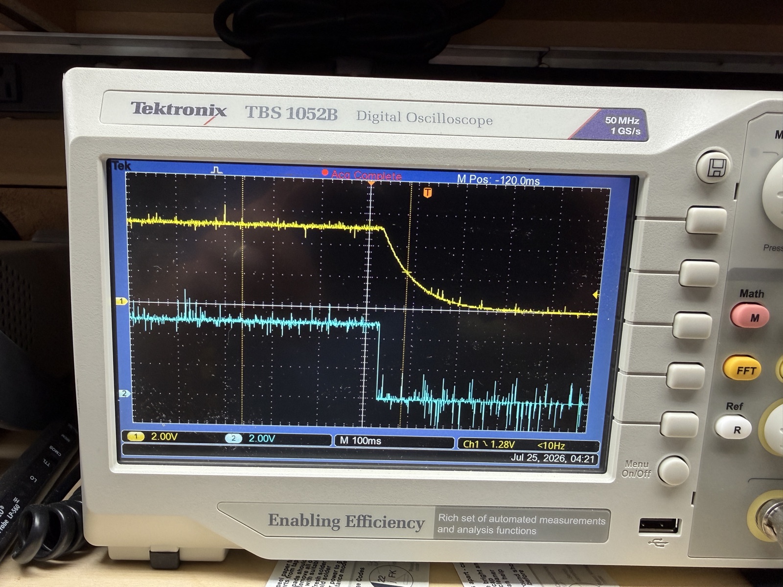
Pin 12 snaps low as the collapse begins, and +5 decays as a passive RC circuit discharges, which is just the output caps draining into the bulb. I read this as cause and effect. The thesis for a while was that the supply was commanding itself off for one reason or another.
That turned out to be a false lead. It was the inverse: the 5V was going away because the converter had stopped, and the falling supply took the status signal down with it. At least that’s what I think in retrospect.
Recapping both boards
User JeffC on IRIXnet had recapped the same model and documented the capacitor list in thread 4686, which user legodude turned into a clickable DigiKey cart. I ordered it, and over the course of this repair ended up replacing every electrolytic capacitor in the supply, both boards, including the C108/C109 bulk pair.
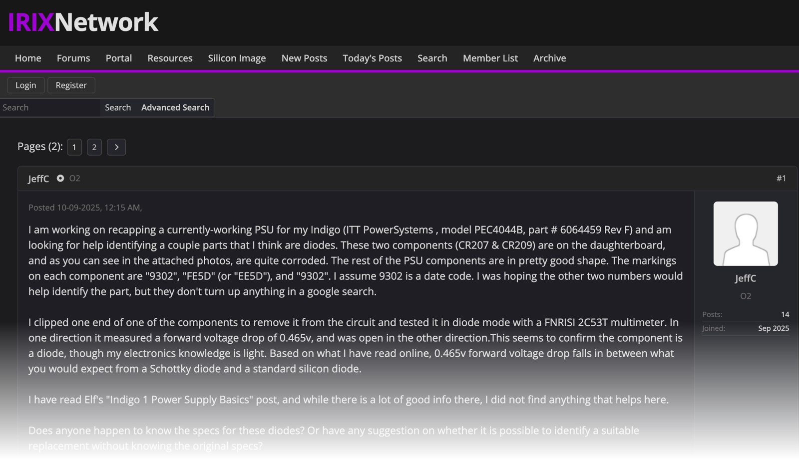
JeffC’s opening post on IRIXnet. Click through for the full thread.
Verify values against your own board. JeffC’s supply (6064459 Rev F) has C127 = 47µF 50V; mine (6064459 Rev C) is 120µF 35V. Same part number; different revision. For what it’s worth, my control board’s silkscreen carries its own assembly number, 6202805 Rev B, so check the label on the case, not just the boards.
I did the control board first and confirmed the supply still ran before touching the main board. One board at a time controls the blast radius; when something changes, you know where you last touched.
Before touching anything I made detailed diagrams of pinouts, cap locations, and cap orientations (the blue marks on the component map below show which way each negative terminal faces). In spite of all that, one cap still went in backwards and one went into the wrong location. Both were caught before power-up, one by inspection against the diagrams and one by measurement with the ESR70. The diagrams didn’t prevent the mistakes, but they made them easy to find.
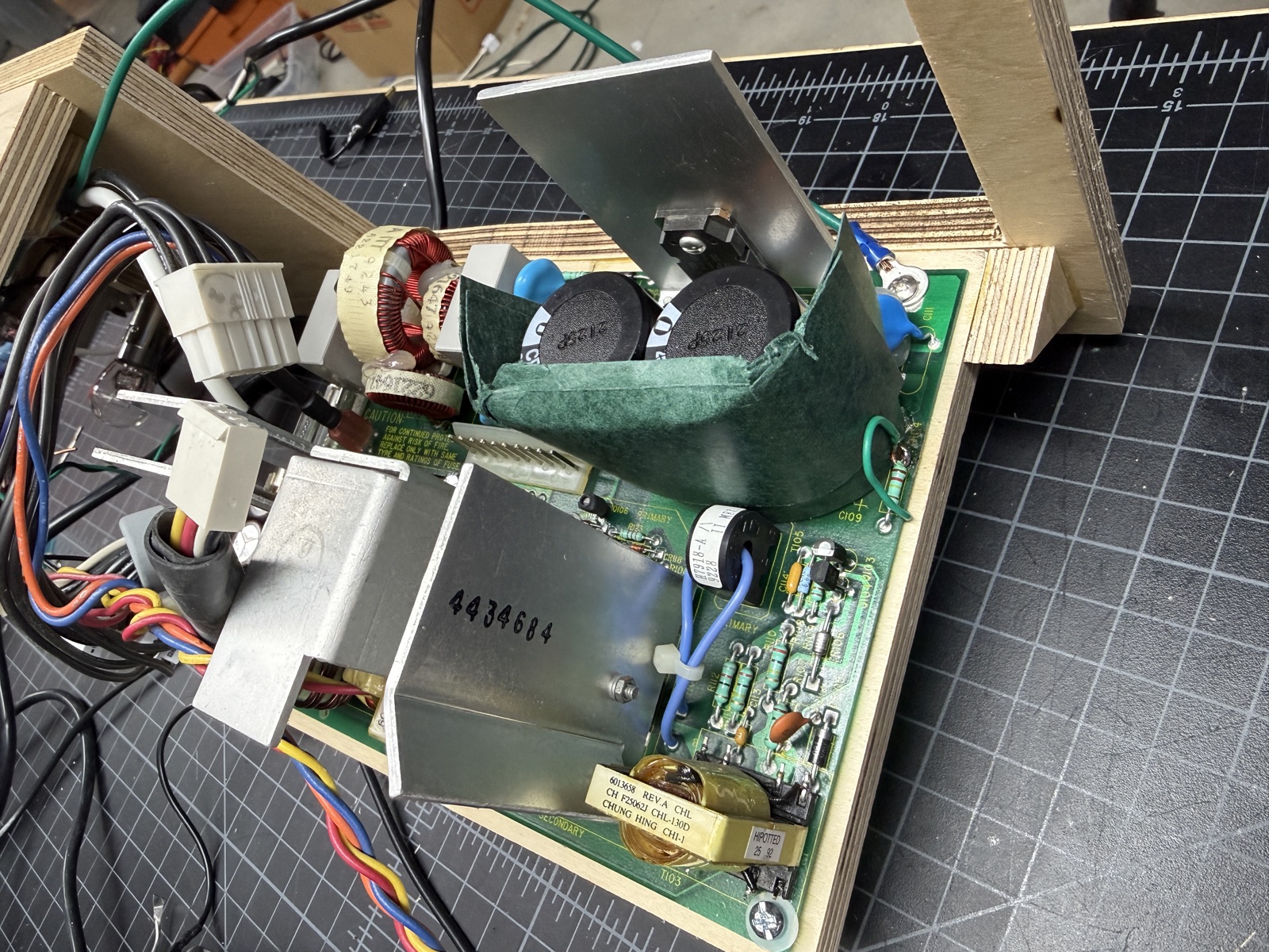
Cap extraction on this board is not easy. The wide heat-sinking traces pull heat away from the joint, and the 33-year-old joints will not let go with ordinary desoldering. The only sequence that worked was to flood the joint with fresh solder, wick it off, flood again, wick again, then walk heat between the leads while pulling gently on the part from the other side of the board. Several I had to just rock one side out first, then work on the other. All the leads were bent over when the components were installed, and as a result the board is ripe for destruction during this process.
Several times I lost the cap in the extraction and could not measure it.
The jig helped by holding the board upright, but you almost always wanted another hand: applying heat on one side, pulling from the other. In retrospect, screwing the jig to the bench might have been a good way to go.
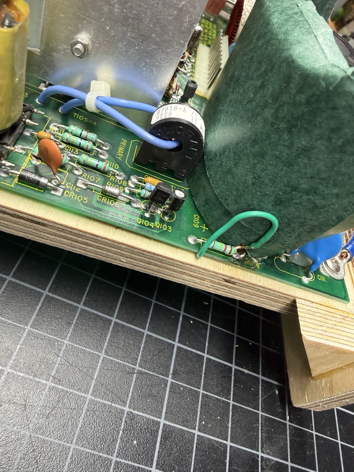
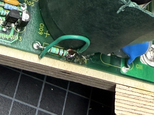
While pulling C108 and C109 I ripped a 2.5mm trace off the component side (C109 to a neighboring resistor) and a few pads with it. The board is two-layer with plated-through holes, and usually the trace for a given lead runs on one side of the board or the other, though sometimes both were on the bottom side (the more favorable case).
A destroyed pad on the side with no trace loses nothing; the barrel still carries the connection, and every such site here continuity-verified fine. When the pad or trace on the connected side is destroyed, you need a bodge wire. For the C109 break I ran insulated 20AWG from the cap terminal on the back side of the board, lead-to-lead to the resistor leg. High power boards are generally built this way, with only two trace layers. At least the old ones I am aware of are.
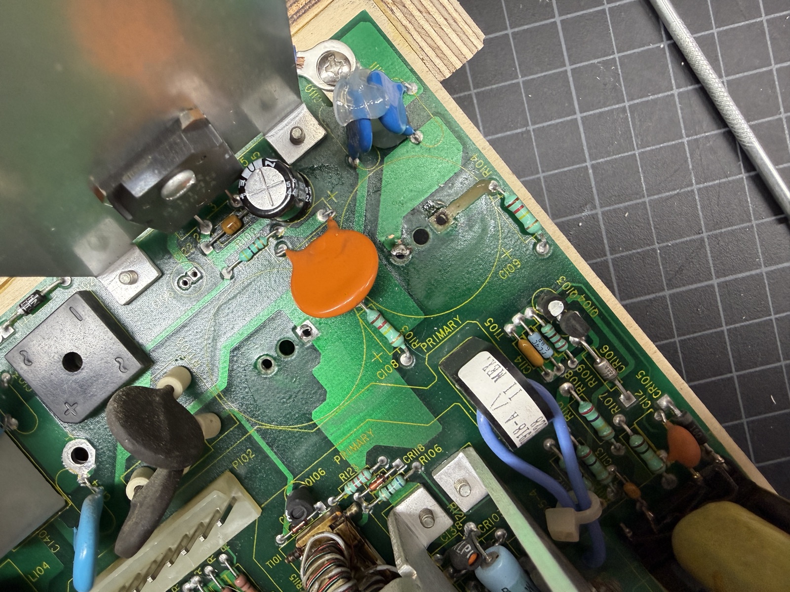
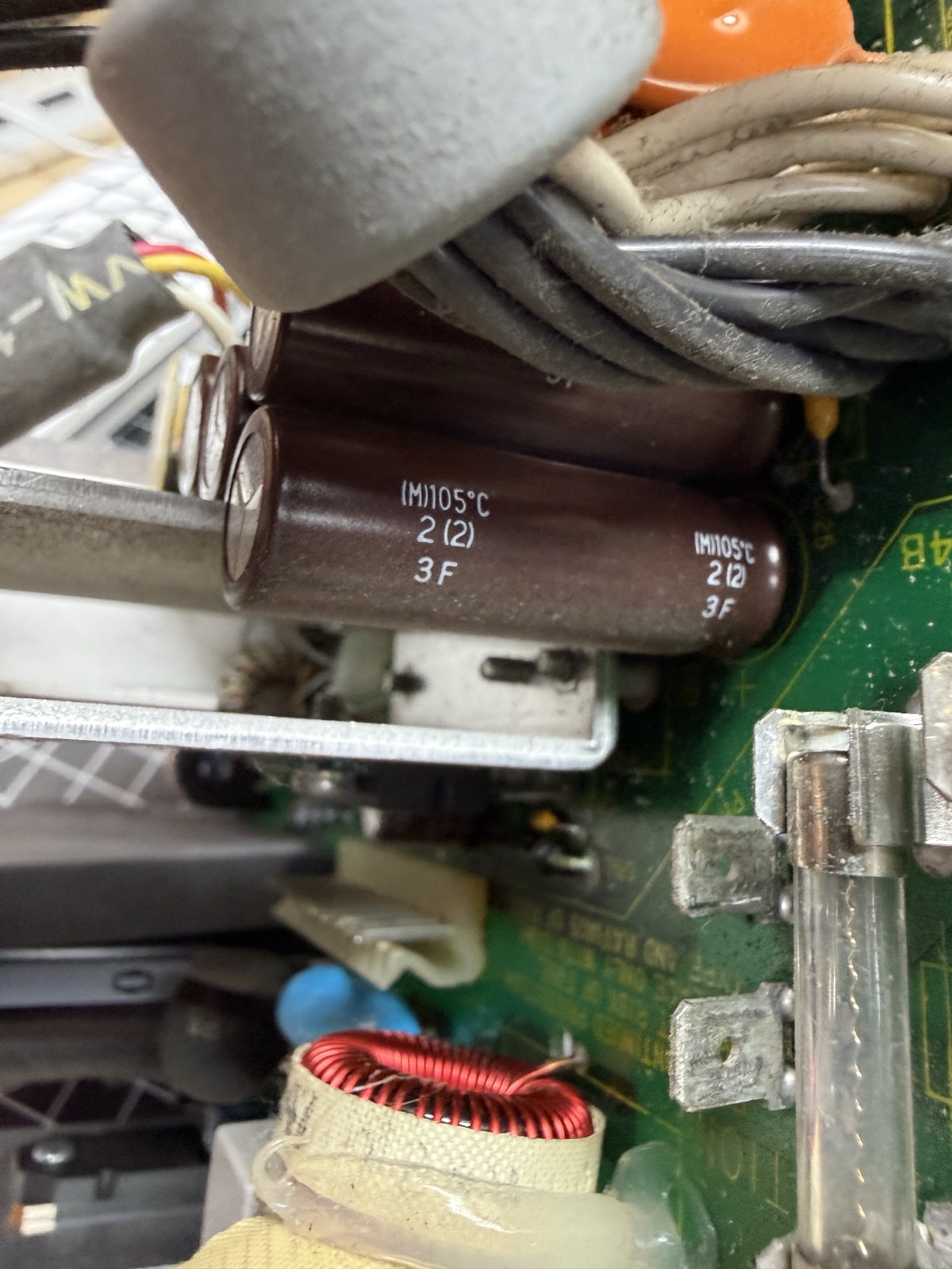
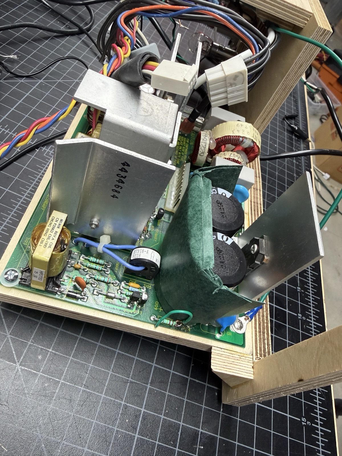
The two big bulk caps are C108 and C109. Their numbers are hidden under the cans, and as far as I can tell they have never been recorded online before. The caps wear an insulating shroud that may not survive removal (it didn’t for me). Replace it; the control board sits very close to those cans, and that insulator is likely there for a reason. I rebuilt the barrier from Pangda adhesive insulating paper (0.2mm fish paper, in green), formed around the new cans in two layers.
In the end, I’m pretty sure the existing caps were OK
I measured every extracted capacitor that survived removal intact, against fresh baselines taken from the new parts. They were all healthy. C235, a 4700µF part, read 4894µF at 0.05Ω ESR after 33 years, better than its replacement. C233: on spec, 0.02Ω. Two of the four 5V output filters: fine (the other two got mangled coming out).
I had also verified the output filter bank in place before it came out, with an AC-coupled scope on the +5 rail, and hit two measurement traps in the process. At slow sweep speeds in scan mode the display draws a min/max envelope: the rail looks like 400mV with a lot of noise, but as Claude pointed out, it’s meaningless. A switching power supply is very noisy, and the noise you see in the photos was actually induced into the ground leads, verified by disconnecting the test lead: the noise stayed.
And most of what you see even at proper settings (10µs/div, bandwidth limit on) is the probe’s ground-clip loop picking switching edges out of the air.
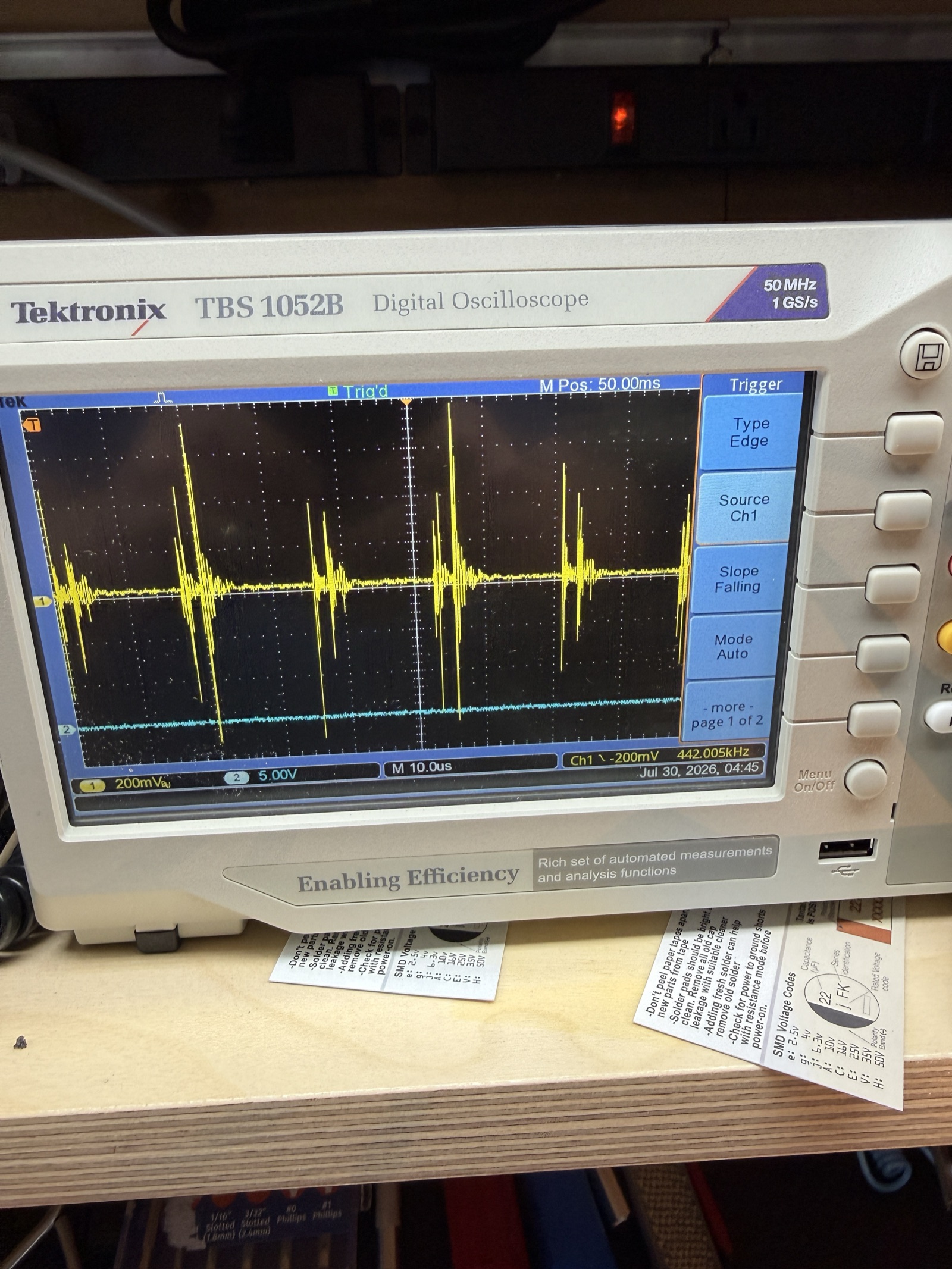
So the recap was likely preventive maintenance. Worth doing, and it should be good for decades, but the caps were probably not the fault.
The only part I conclusively found bad: CR111
During final testing the supply failed completely. It would not start after power cycles or after sitting unplugged overnight. This was different from the warm-shutdown behavior, and it meant a hard component failure that could now be found. It was honestly a bit depressing after weeks of it “kind of” working.
The most likely remaining component, according to Claude and the reference sources, was the zener diode CR111 next to C127. I ordered one and waited. When a friend was around, he helped as the third hand, pulling on the diode lead while I heated the joint. Once it was out, I tested the diode and it was a dead short, measured in both directions. When you actually find a hard-failed part, that is when you start to get excited about the project again. I had a similar experience with my NCR PC4 and its obviously exploded capacitor.
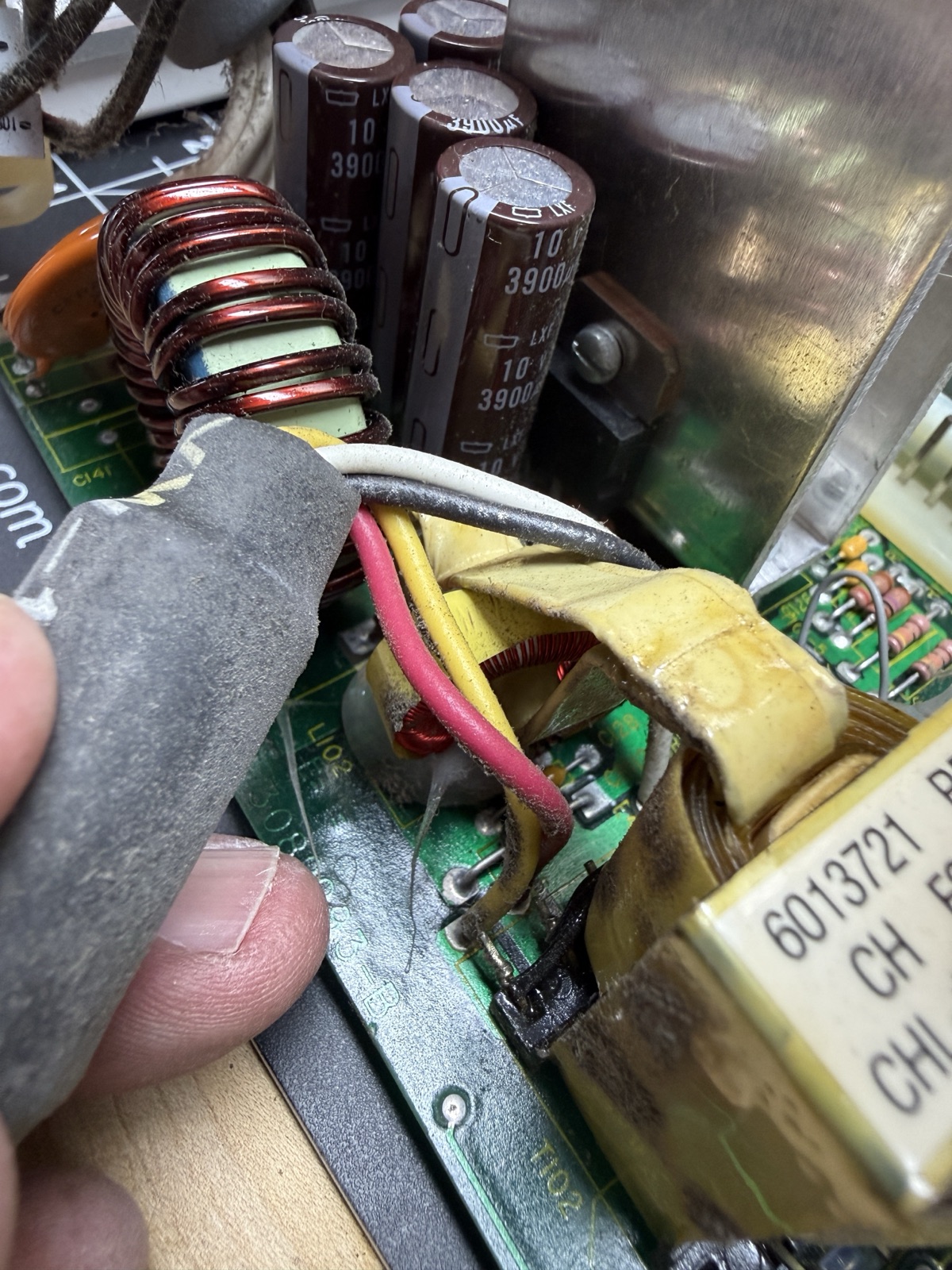
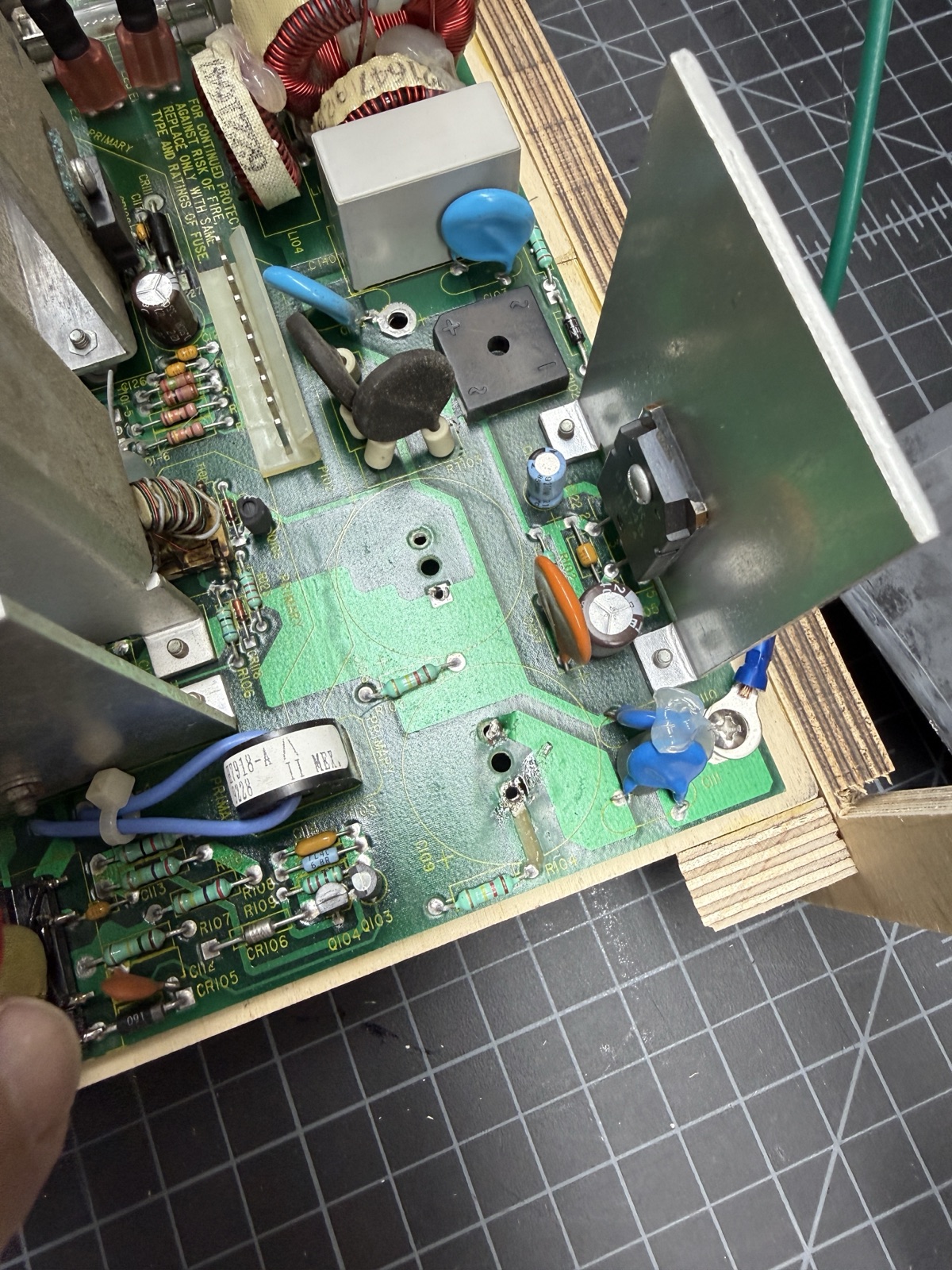
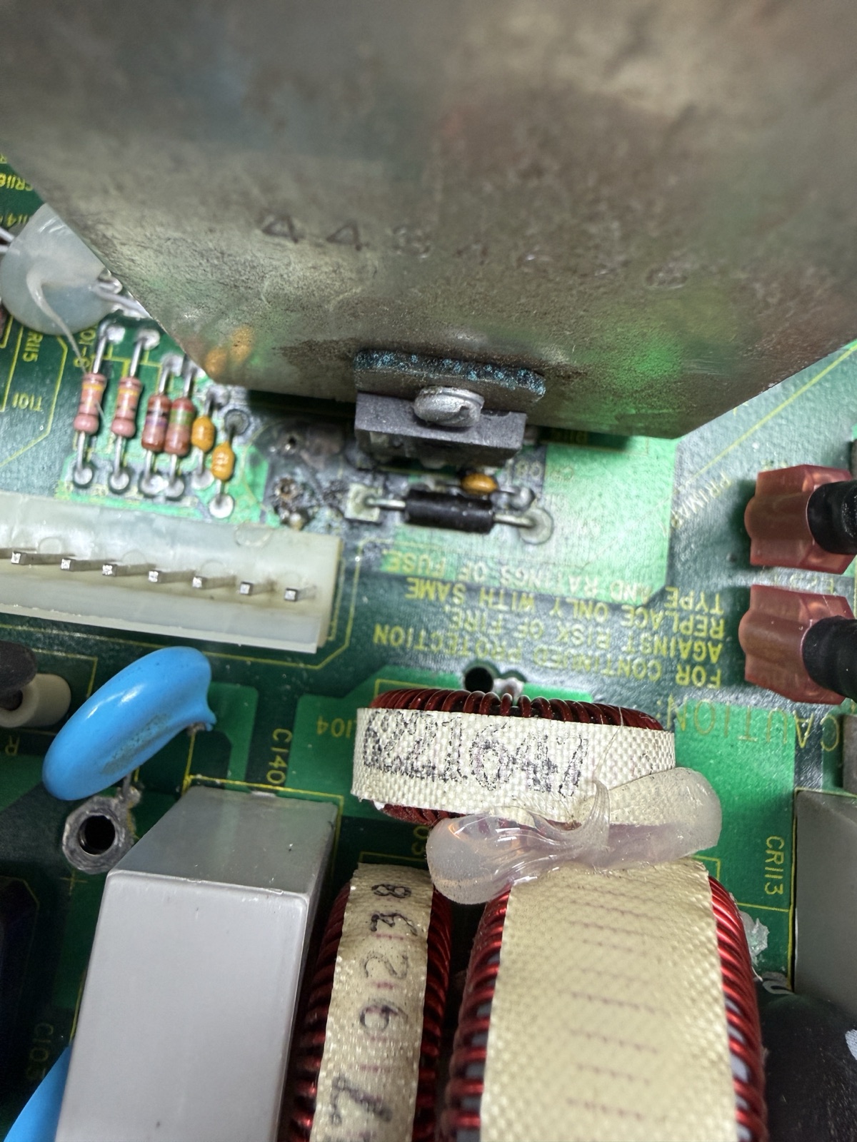
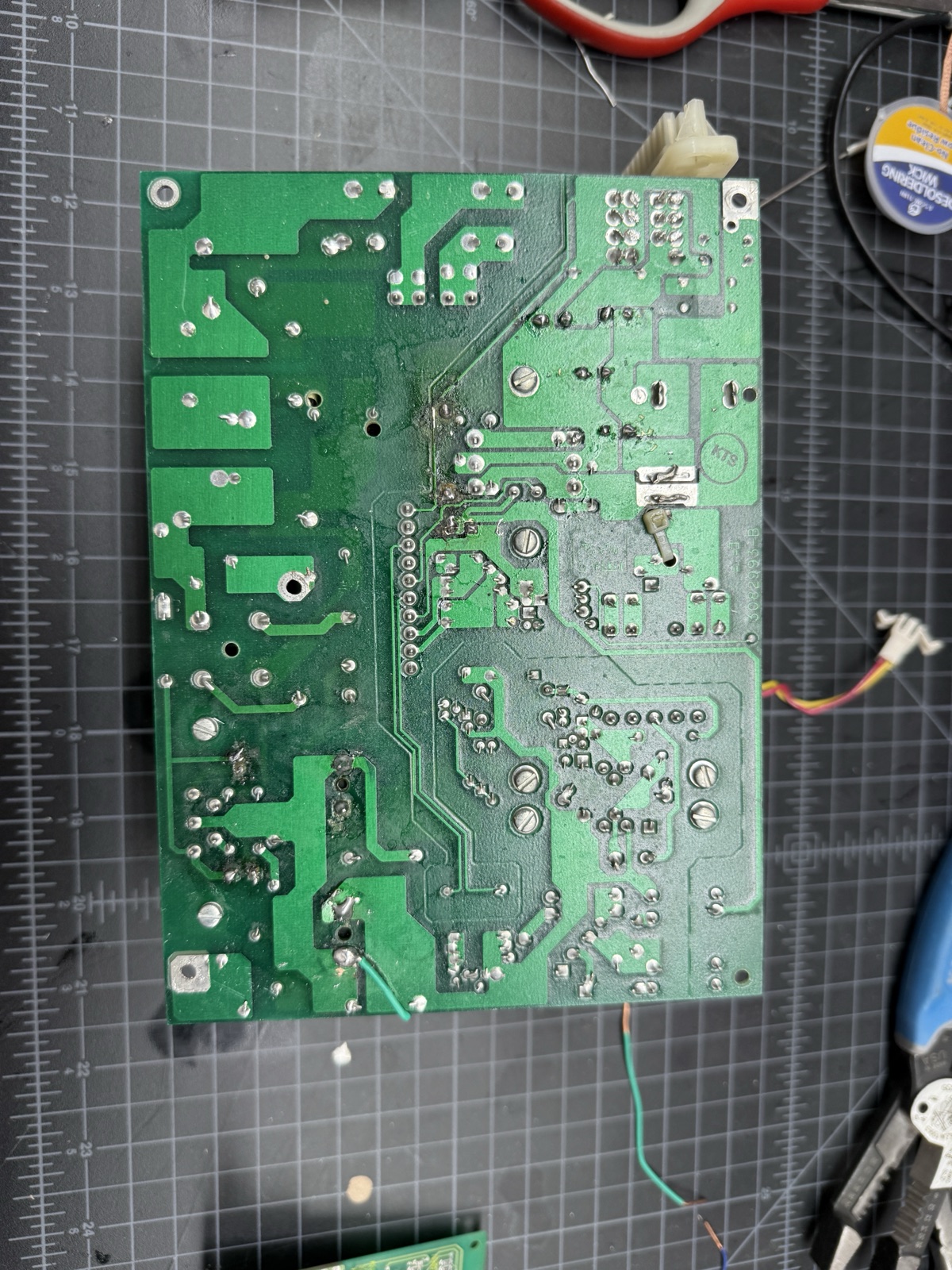
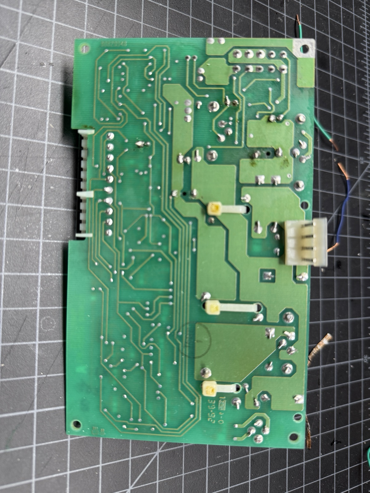
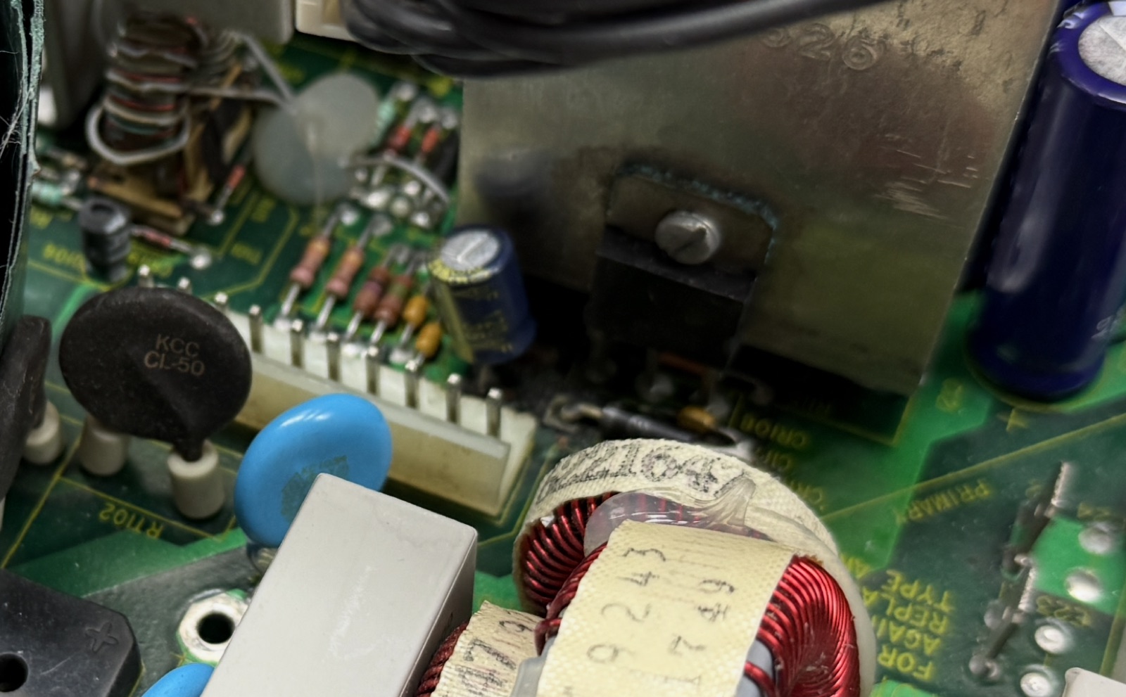
On the Indigo, the back side of the board where the zener diode lives was browned. I had noticed that initially, but honestly that’s not completely unusual for old PSU boards. It was, however, the only discoloration anywhere on either board. The part had been running hot for a long time.
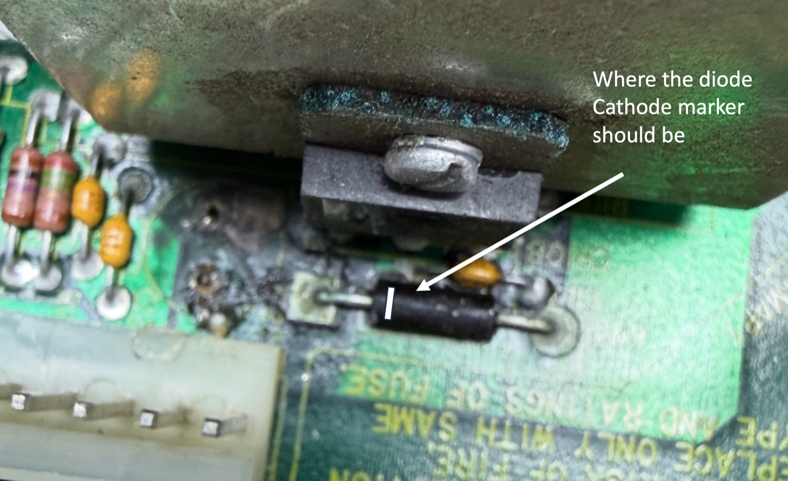
Two old forum reports then made sense. In Elf’s SGUG thread, two other owners hit this same failure. steeph (2021) found the same burnt-looking unmarked diode in the same position, board charred underneath, and never got an answer. Archaic (2021) had the adjacent 120µF cap, C127, leak all over everything, corroding the diode; he identified it as a 15V zener, 1N5352 type, and his thread also ends unresolved. The capacitor C127 is a documented leaker in this design, its electrolyte corrodes the zener below it, and the zener degrades, leaking progressively when warm, until it finally fails short. I can’t honestly say I had the leaking cap, but clearly that’s a part that runs very hot.
A zener that leaks when warm drags the controller’s supply toward the 7.6V undervoltage-lockout stop threshold: the converter quits and the rails coast down, which is the pin 12 capture. After a couple of minutes of cooling, it recovers. It explains why the supply died warm after running a while, why the timing wandered as the part degraded, and why it finally failed short and went silent. The screen noise and the scratchy speaker trace to the same part (the audio path runs on the ±12 analog rails). Every symptom this machine showed came from one inexpensive component that had been overheating for years. The supervision circuit I had blamed was only reporting the shutdown, not causing it.
Replacing CR111
The replacement is a 1N5352B: 15V, 5W axial zener. Orientation matters, and the part gives you no help. The missing band is unfortunately normal for this part in this machine. Elf checked his own supplies and found the same unmarked matte-black package, so nobody has ever read a band on this component. I couldn’t recover the orientation from the old one by testing it, because it was shorted in both directions.
The board convention is cathode to the square pad, anode to the round pad. This is established empirically by looking at other diodes on the board.
Archaic tried it the other way and got “the loudest screeching noise that I have ever heard from a power supply,” so don’t repeat that experiment. After that his trek was apparently over.
Photograph the area before extraction, cross-check against another banded diode on your board (they all point band-to-square-pad), and if corrosion has eaten the silkscreen, the pad going to ground is the anode. In my case the old part had no marking to read and tested bad in both directions, so orientation couldn’t be recovered from the part at all. I went with the board convention, cathode to the square pad like every other diode on the board, and it turned out to be correct.
Replace C127 in the same session; for me it was the last cap left to replace. For some owners it was that cap leaking that caused the problem with the zener. For me I think it was just heat.
The result
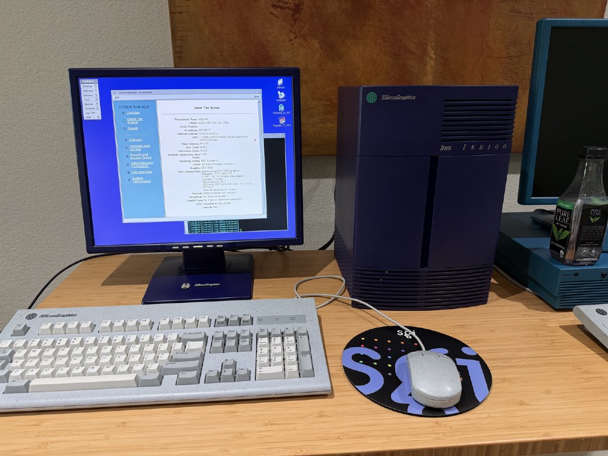
With the new zener in, last caps in, back on the jig, the supply started and ran an hour-plus without issue, then restarted cleanly while warm, the same restart that used to fail (sometimes). Reassembled, reinstalled, and the Indigo boots. Normal startup tune, and for the first time in years, no scratch from the speaker and no noise on the screen, which confirms those were power supply symptoms all along. The photo at the top of this article is the machine back in service, running on its matching retro-reimagined display.
The component map
Every electrolytic on both boards, with original values, all replaced by the end, plus CR111, the failed zener. Verify every value against your own silkscreen before ordering; this is a Rev C supply, and JeffC’s Rev F differs in at least one value.
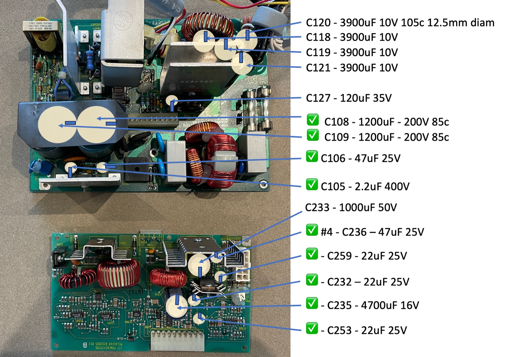
| Designator | Board | Original value | Notes |
|---|---|---|---|
| C232, C253, C259 | Control | 22µF 25V | Housekeeping/bias |
| C235 | Control | 4700µF 16V | Old part measured 4894µF, 0.05Ω ESR: healthy |
| C236 | Control | 47µF 25V | |
| C233 | Control | 1000µF 50V | Old part healthy, 0.02Ω ESR |
| C105 | Main | 2.2µF 400V | Primary side |
| C106 | Main | 47µF 25V | UC2845 Vcc reservoir; use your best low-ESR part here |
| C108, C109 | Main | 1200µF 200V 85°C | The bulk pair; designators hidden under the cans |
| C118-C121 | Main | 3900µF 10V | 5V output filters; old parts verified healthy |
| C127 | Main | 120µF 35V | The leaker that killed CR111. 47µF 50V on JeffC’s board, so check yours |
| CR111 | Main | 15V 5W zener (1N5352) | The only failed part in the supply. Cathode to the square pad |
The parts order
The complete bill of materials for the next PEC4044B owner. Replacements carry higher voltage ratings than the originals where the modern part in the same footprint allows it.
| Manufacturer part | Maker | Value | Qty | Destination |
|---|---|---|---|---|
| UVZ2W2R2MPD | Nichicon | 2.2µF 450V | 1 | C105 |
| EEU-FR1H470B | Panasonic (FR series) | 47µF 50V | 1 | C106 |
| ESW476M035AE3AA | KEMET | 47µF 35V | 2 | C236, plus a spare |
| ESC226M035AC3AA | KEMET | 22µF 35V | 3 | C232, C253, C259 |
| UHE1C472MHD | Nichicon | 4700µF 16V | 1 | C235 |
| SLP122M200E4P3 | Cornell Dubilier | 1200µF 200V snap-in | 2 | C108, C109 |
| UPW1H102MHD | Nichicon | 1000µF 50V | 1 | C233 |
| ELXZ160ELL392MK40S | Chemi-Con | 3900µF 16V | 4 | C118-C121 |
| EEU-FC1V121B | Panasonic (FC series) | 120µF 35V | 1 | C127 |
| 1N5352B | onsemi/Vishay | 15V 5W zener | 1 | CR111 |
All in, under sixty dollars of DigiKey parts for a supply you cannot buy anywhere, and the part that actually mattered costs about a buck.
Lessons
- The standing community advice for these supplies is a recap, and in JeffC’s case on IRIXnet that is what fixed it (his corroded CR207/CR209 diodes actually tested fine). In my case every measurable cap was fine and the failure was a diode, CR111. Recap as preventive maintenance, but test the diodes when diagnosing. I have another Indigo 1 and honestly, I’m going to start with just the diode and see what happens.
- Old caps age individually. A 33-year-old cap that beat its replacement’s numbers and a shorted zener came off the same board. Workstation-class machines, in my experience, used much better caps than home computers of the same generation. Are the caps bad?
- Instruments mislead in specific ways: a 100W dim-bulb starves a 300W supply, a once-a-second DMM prints voltages that never existed, scan-mode scope displays alias, and ground-clip loops pick up switching noise that isn’t on the rail. Check any alarming measurement with a control experiment.
- Same model does not mean same board. Verify every value against your own silkscreen.
- An unmarked part isn’t necessarily a damaged part, but a browned board under one is a strong hint of where the problem is.
- One board at a time, reassemble, retest. And make the diagrams anyway; mine caught two installation mistakes before power-up.
For the next owner
If your Indigo dies warm, recovers cool, and one day goes permanently silent, measure CR111, the unmarked zener next to C127. The supply’s behavioral model, pinout, and state machine are in Elf’s Indigo 1 Power Supply Basics at the SGUG forums; this repair would have taken far longer without it. steeph, Archaic: if you still have those supplies, check the zener.
Gallery