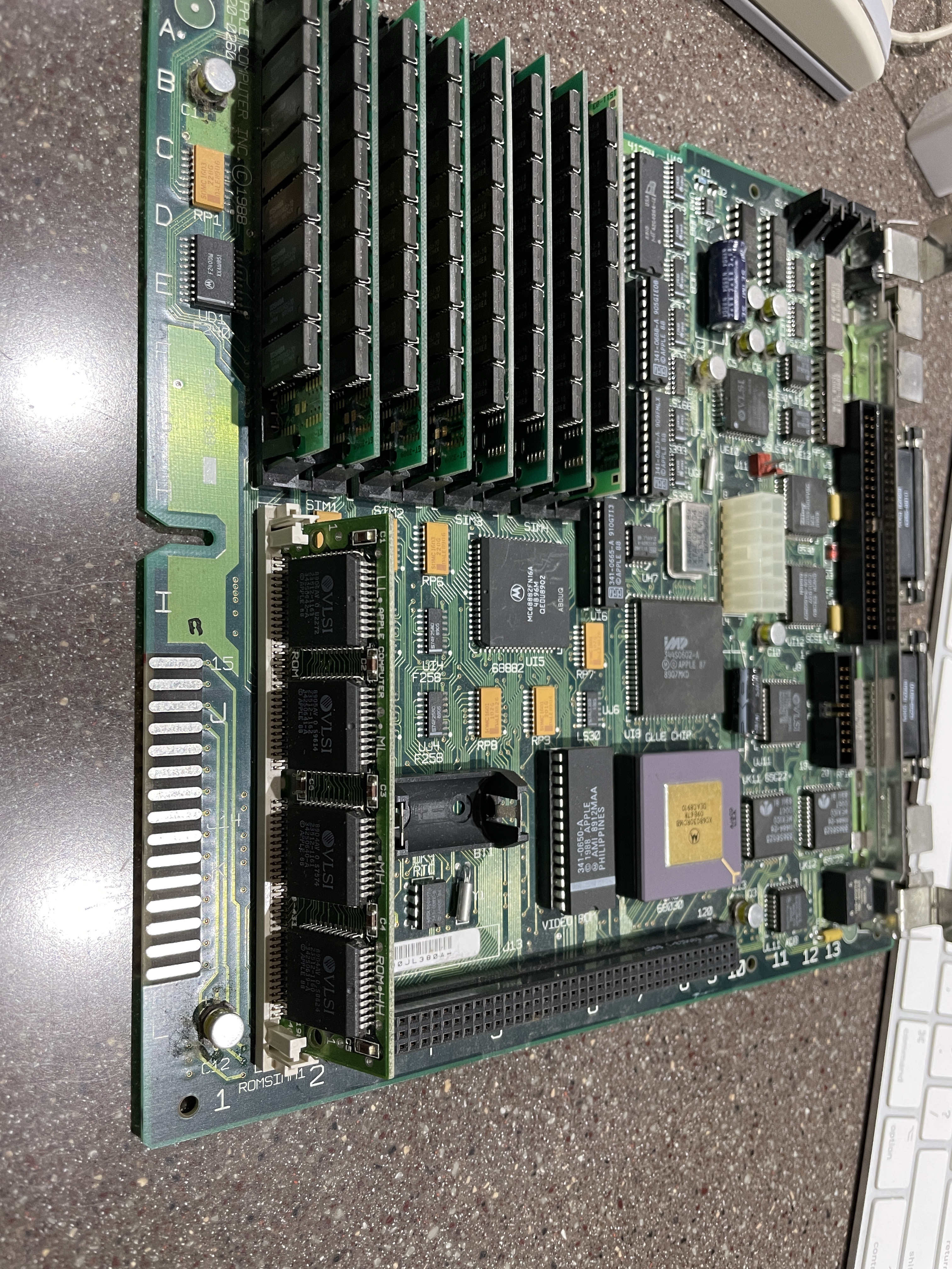
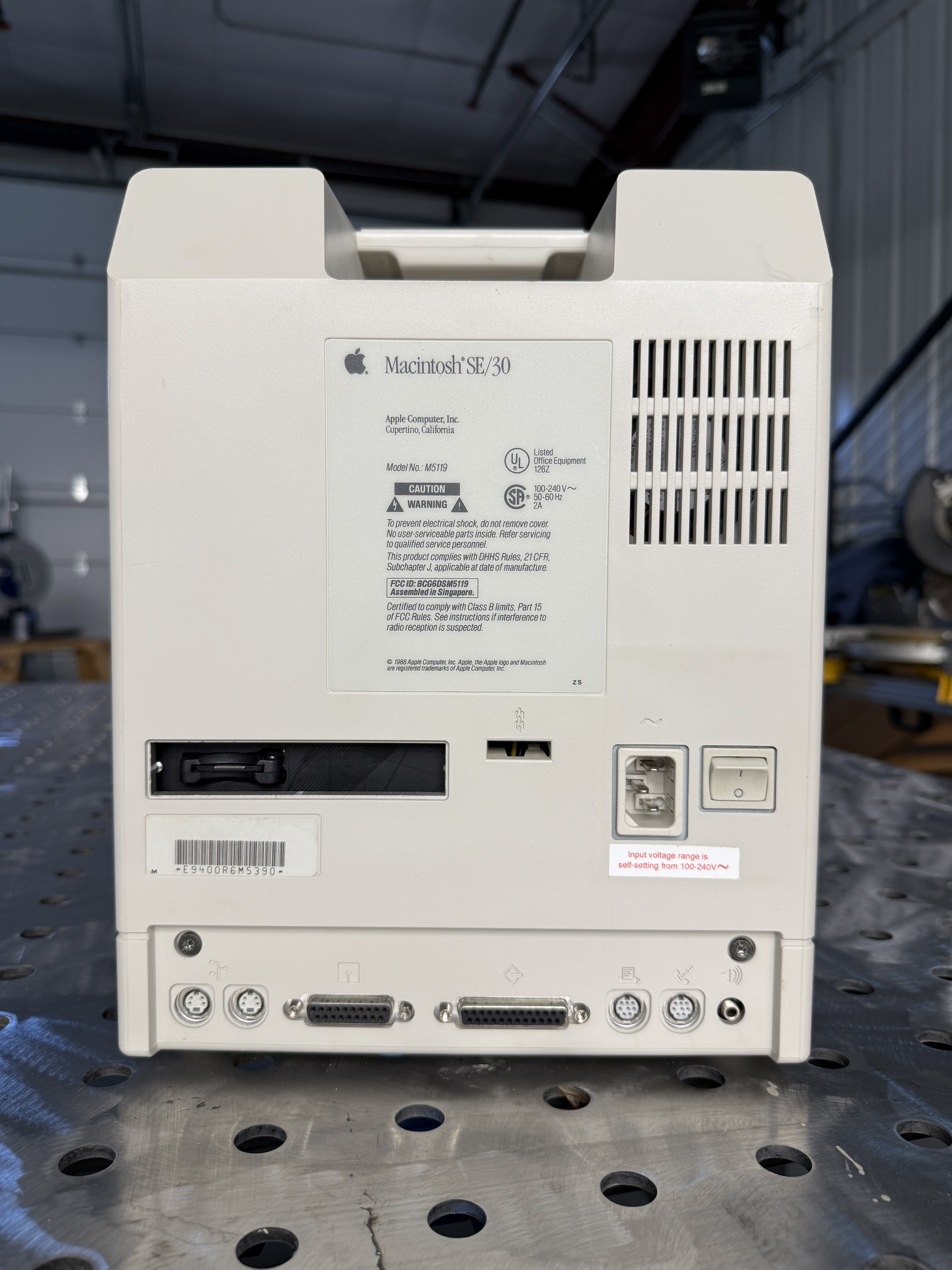
The Macintosh SE/30, released in January 1989, is the machine most vintage Mac enthusiasts point to as the best of the compact era. A Motorola 68030 at 16 MHz, 1 MB of RAM stock (expandable to a then-astonishing 128 MB), a 1-bit 9-inch CRT, and a PDS slot that made it the first compact Mac to support accelerators, video cards, and Ethernet. For a machine in a beige all-in-one shell, the SE/30 punched far above its weight.
It is also, to a fault, a machine designed in the era of surface-mount electrolytic capacitors. Time is the real enemy of any SE/30. The electrolytics on both the logic board and the analog/power board leak, and when they leak they eat traces, kill sound, and — if left long enough — take the SCSI controller with them. This is the story of two SE/30s I bought to get one working.
The Odyssey Begins
I originally found what looked like a working SE/30 on eBay and bought it. The machine would boot from floppy, which is always an encouraging first sign, but the sound was completely dead. Dead sound on an SE/30 is the classic early-warning: it almost always means that the audio-path electrolytics on the logic board have begun to leak and the rest of the filter caps are not far behind.
For a lot of machines in the collection I wait to recap until there’s a specific problem to chase. For Macs, especially compact Macs from the late 80s and early 90s, my approach is: just do it. The electrolytic capacitors Apple specified in this era were not high-quality parts, and they will fail. The only question is whether you recap proactively or wait until the leakage has eaten traces and taken the SCSI chip with it.
Spoiler: I waited a little too long to figure this out.
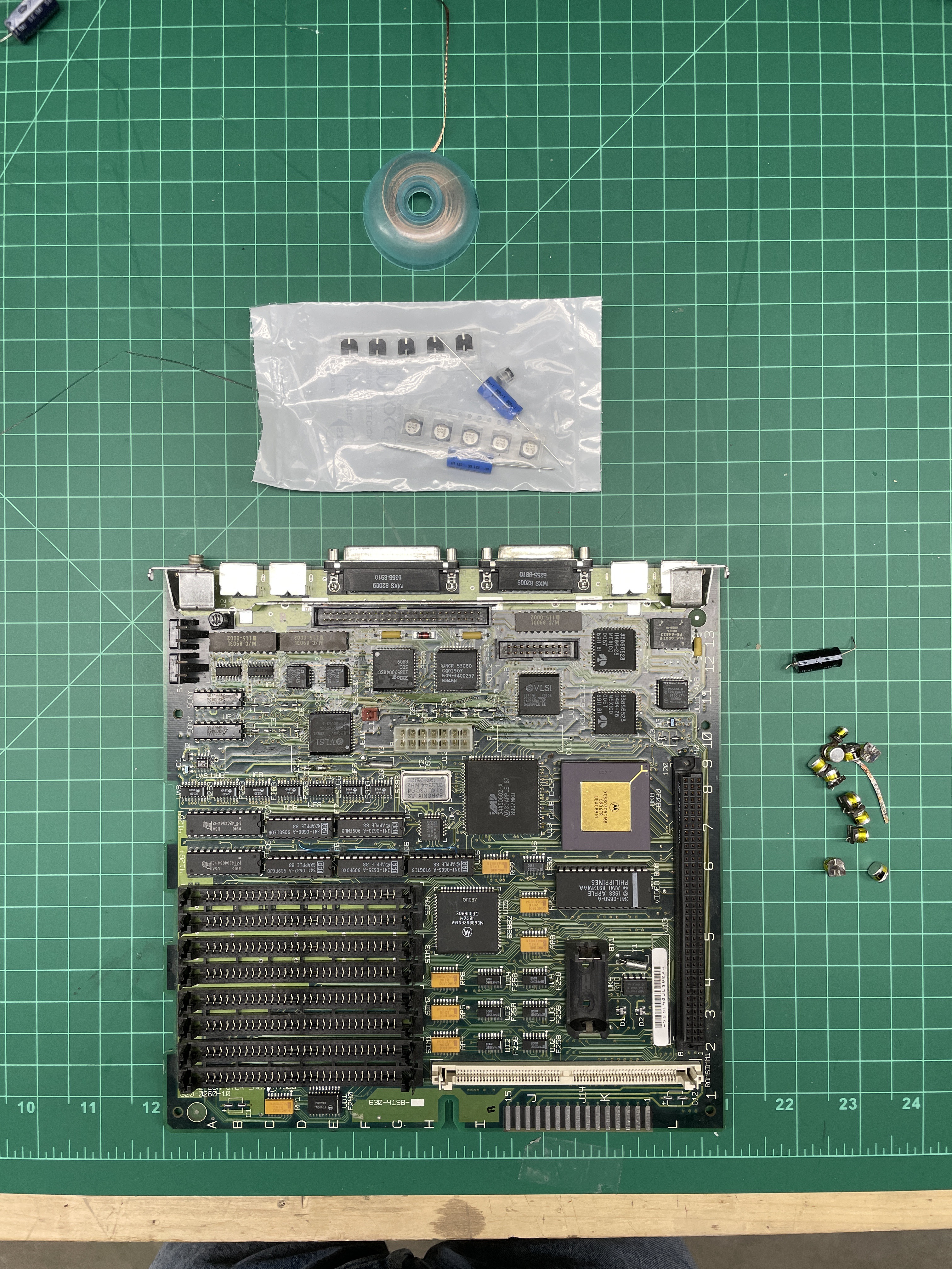
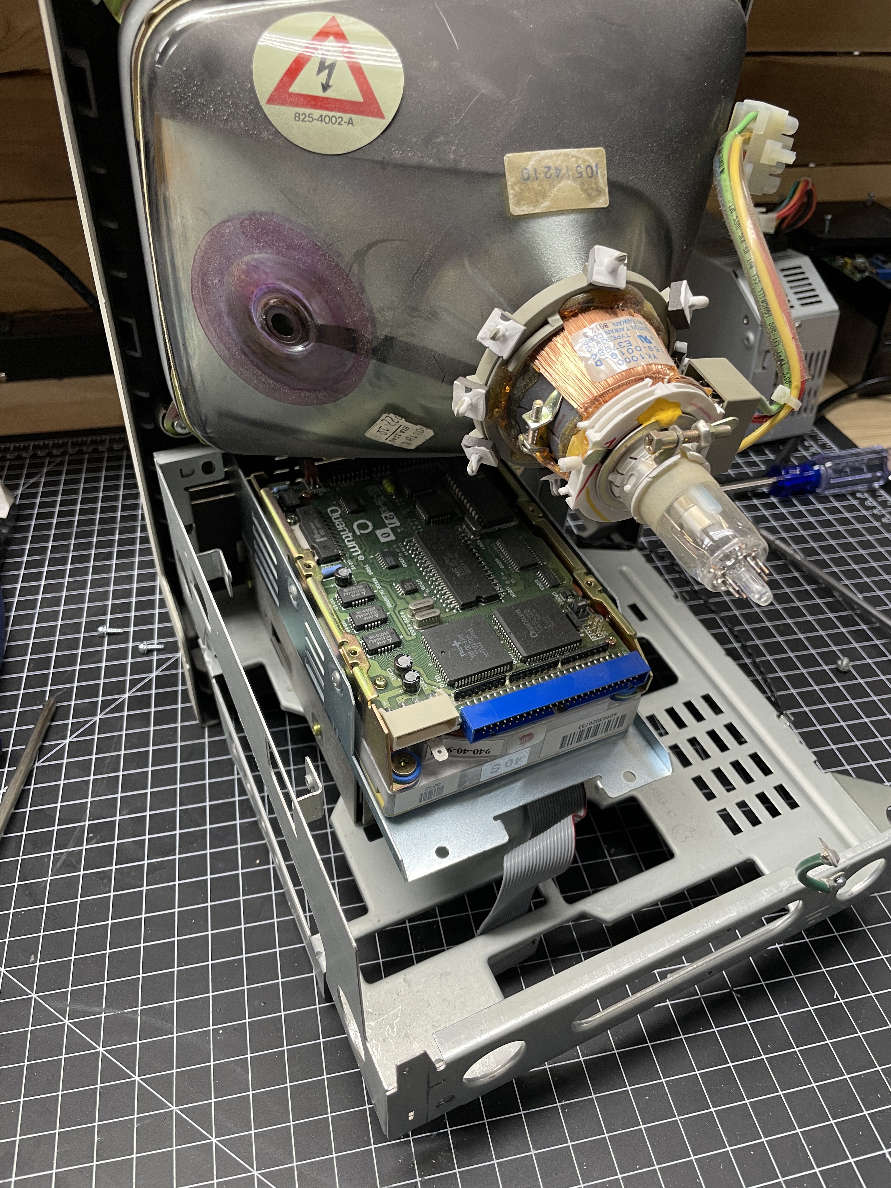
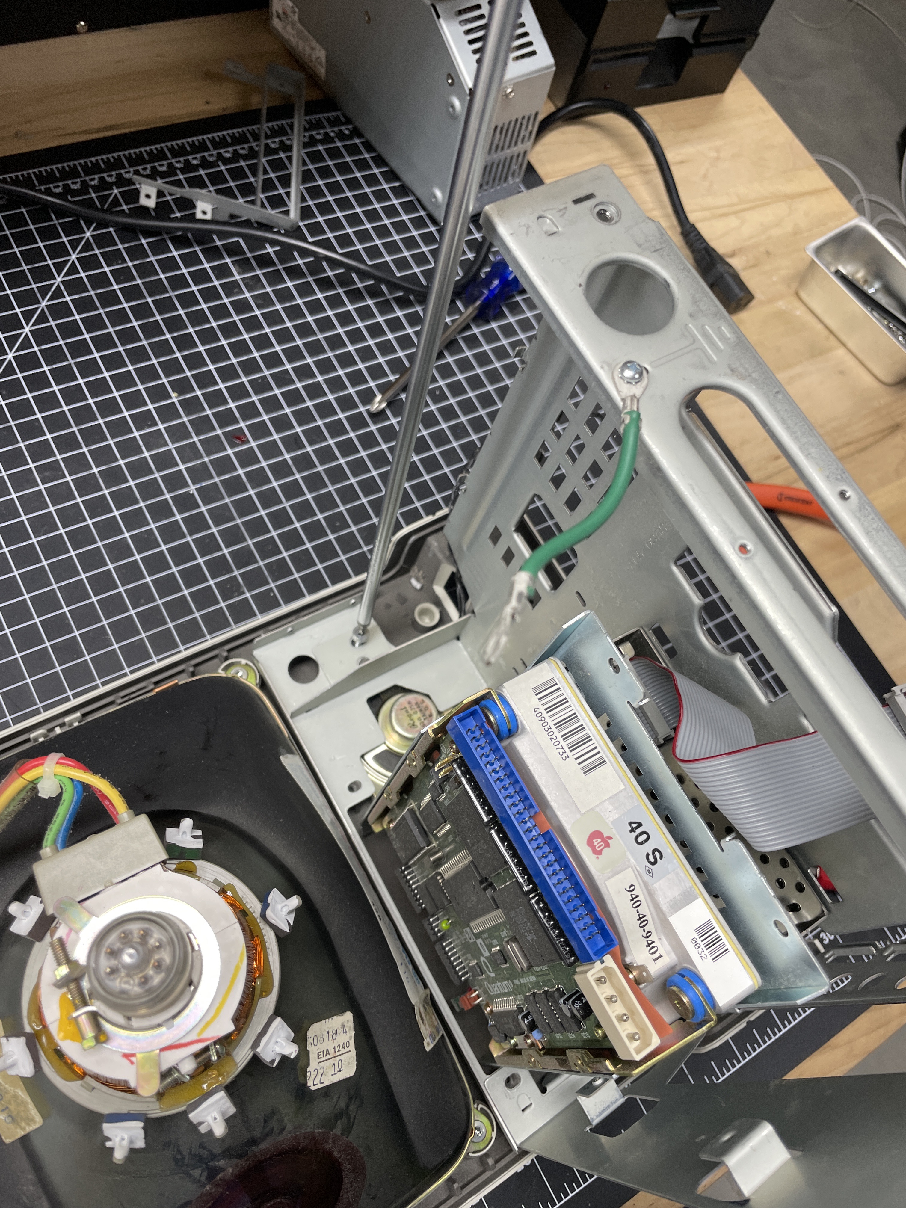
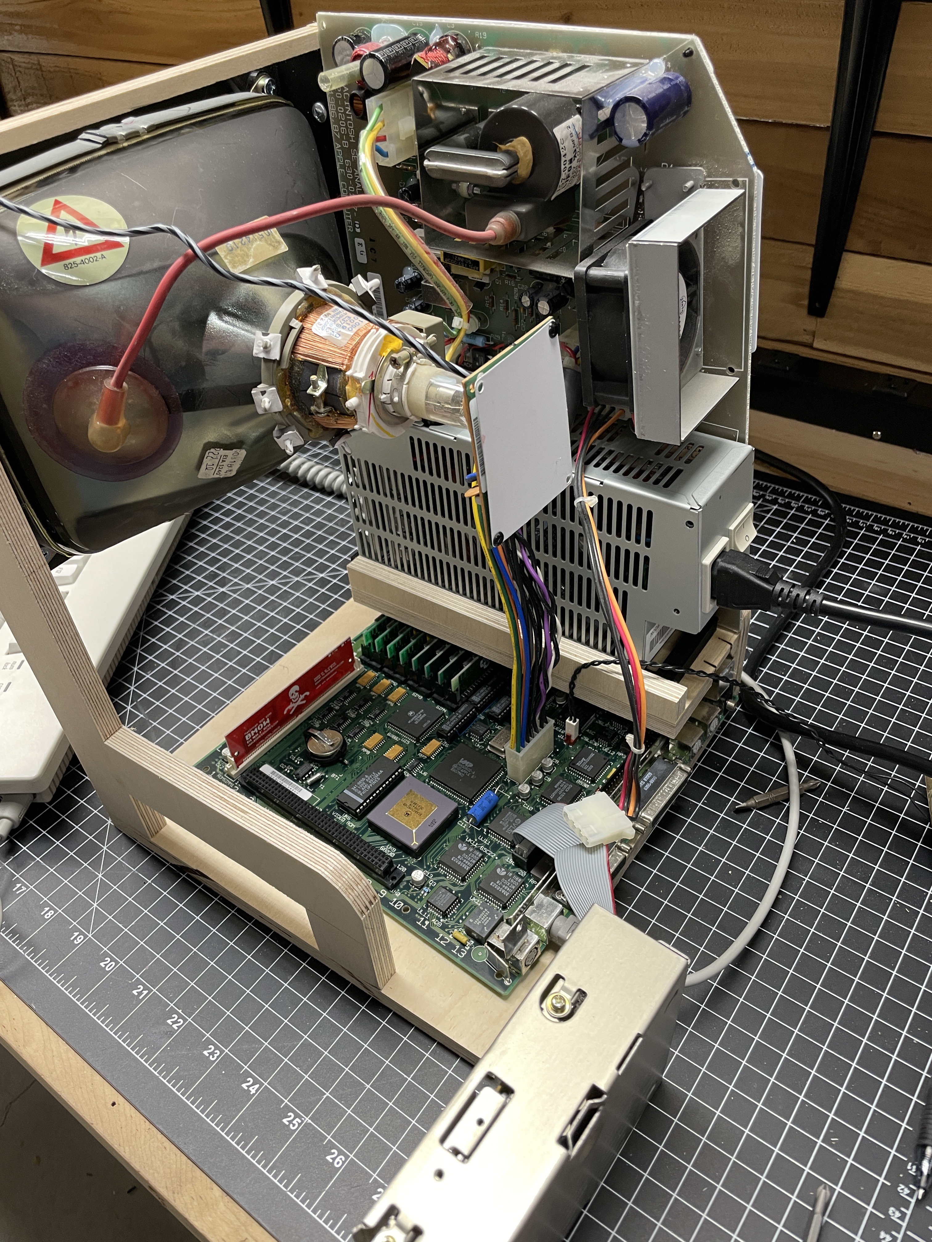
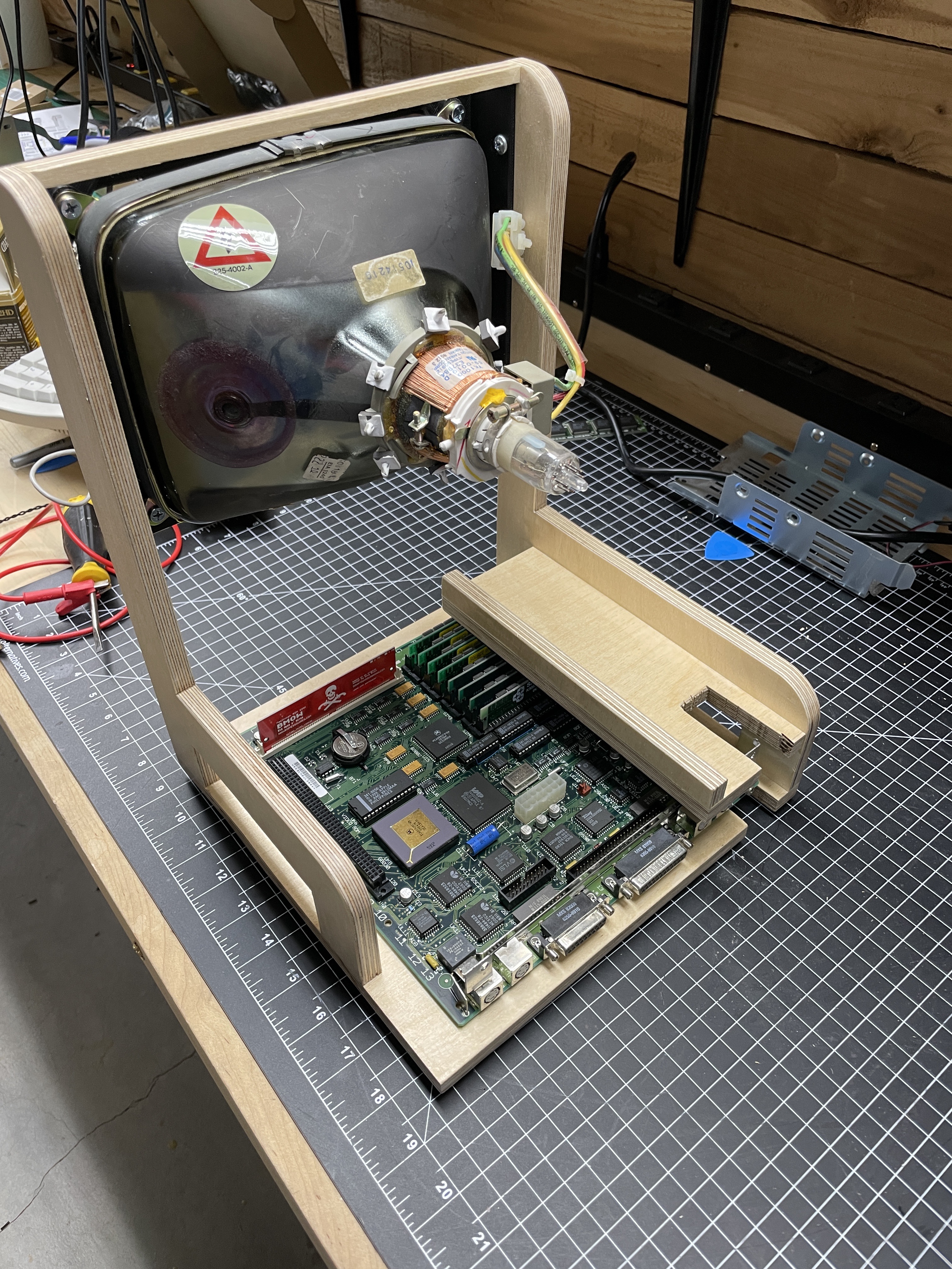
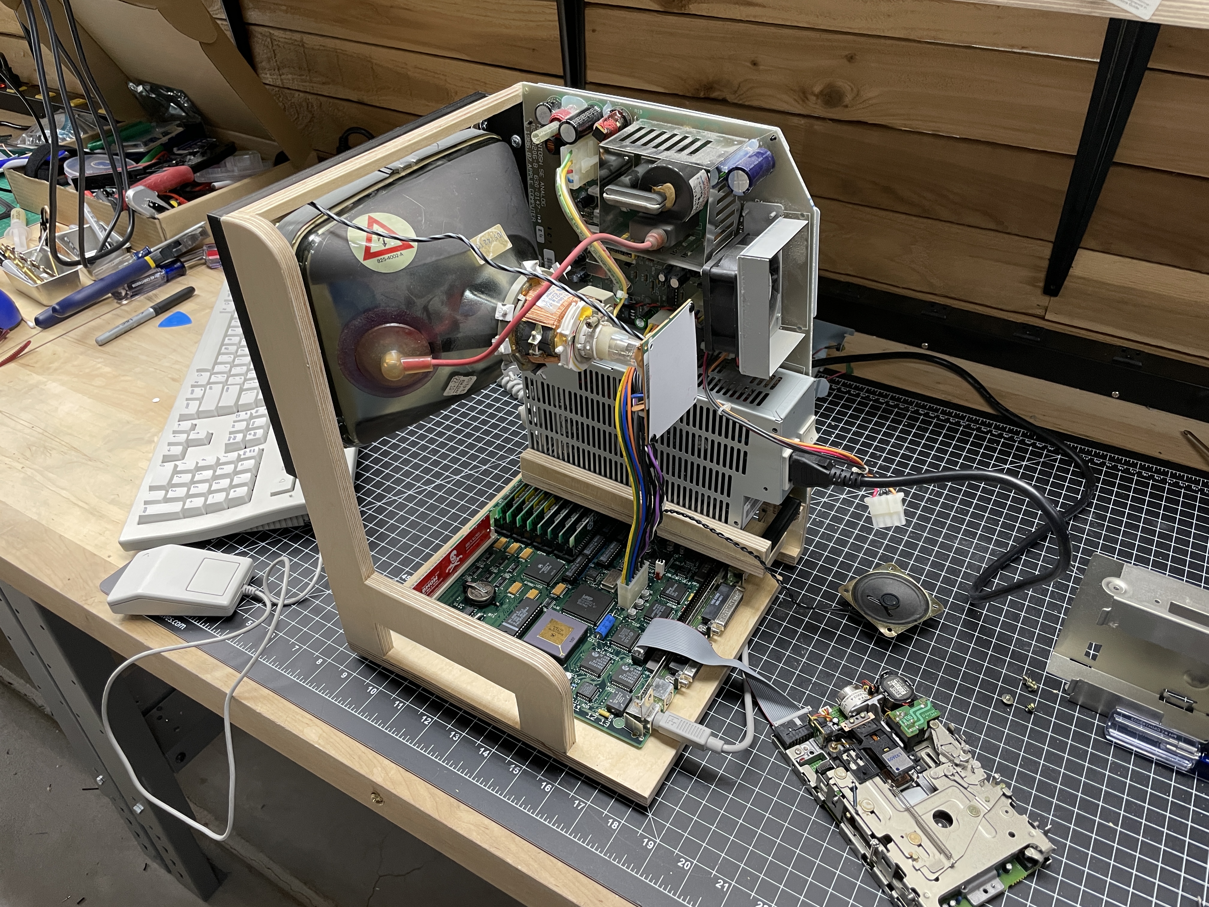
Building a Jig
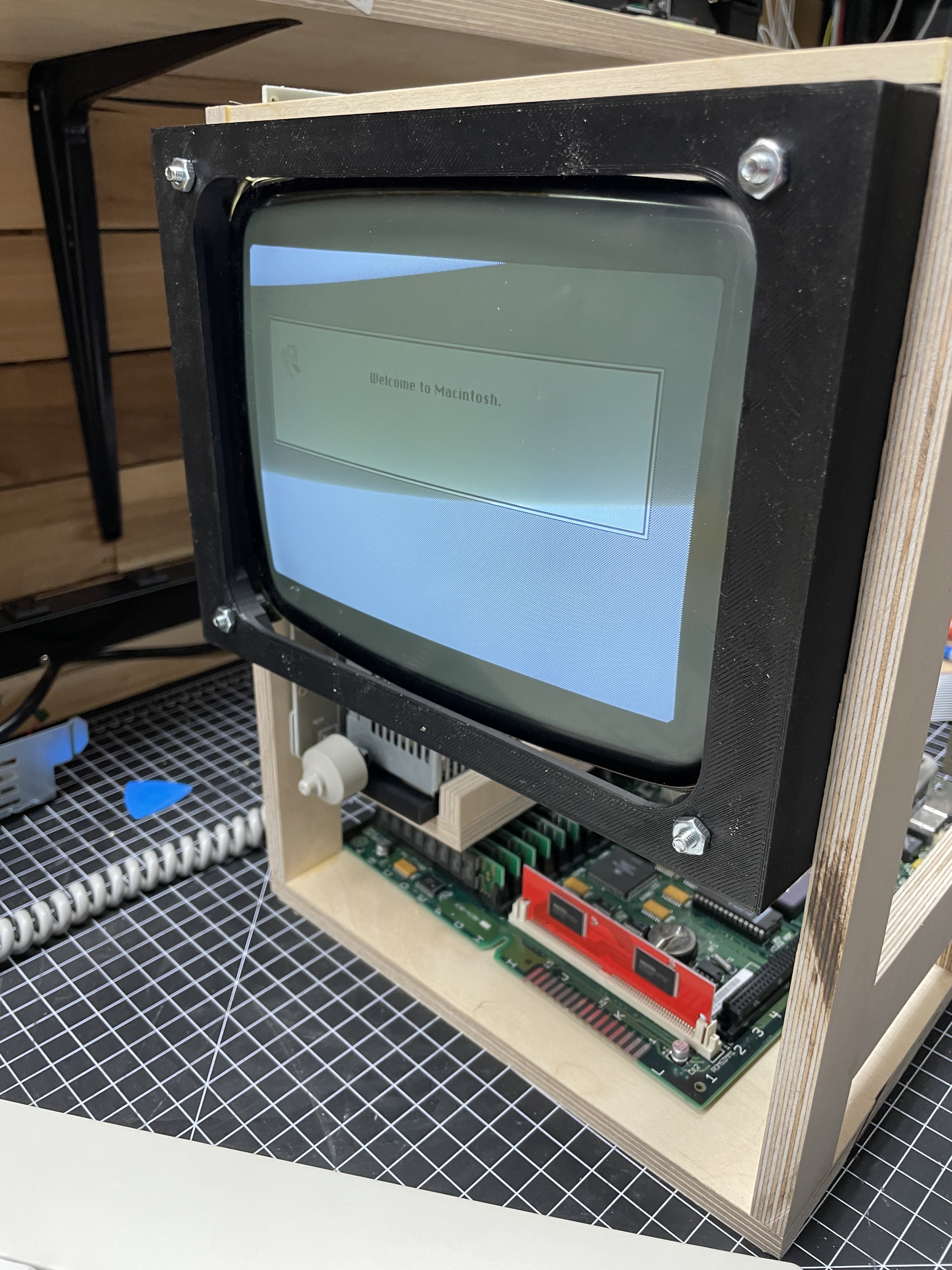
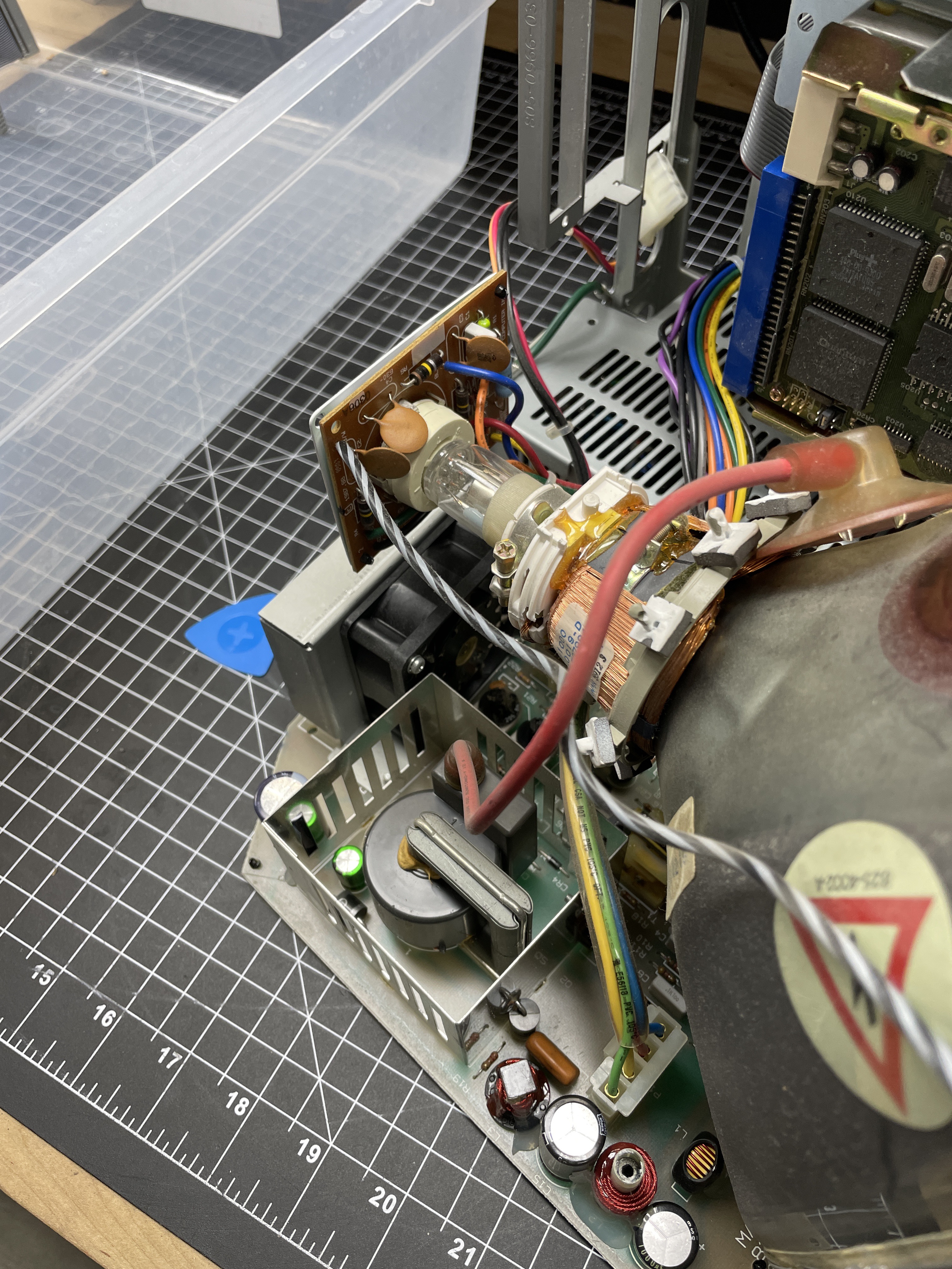
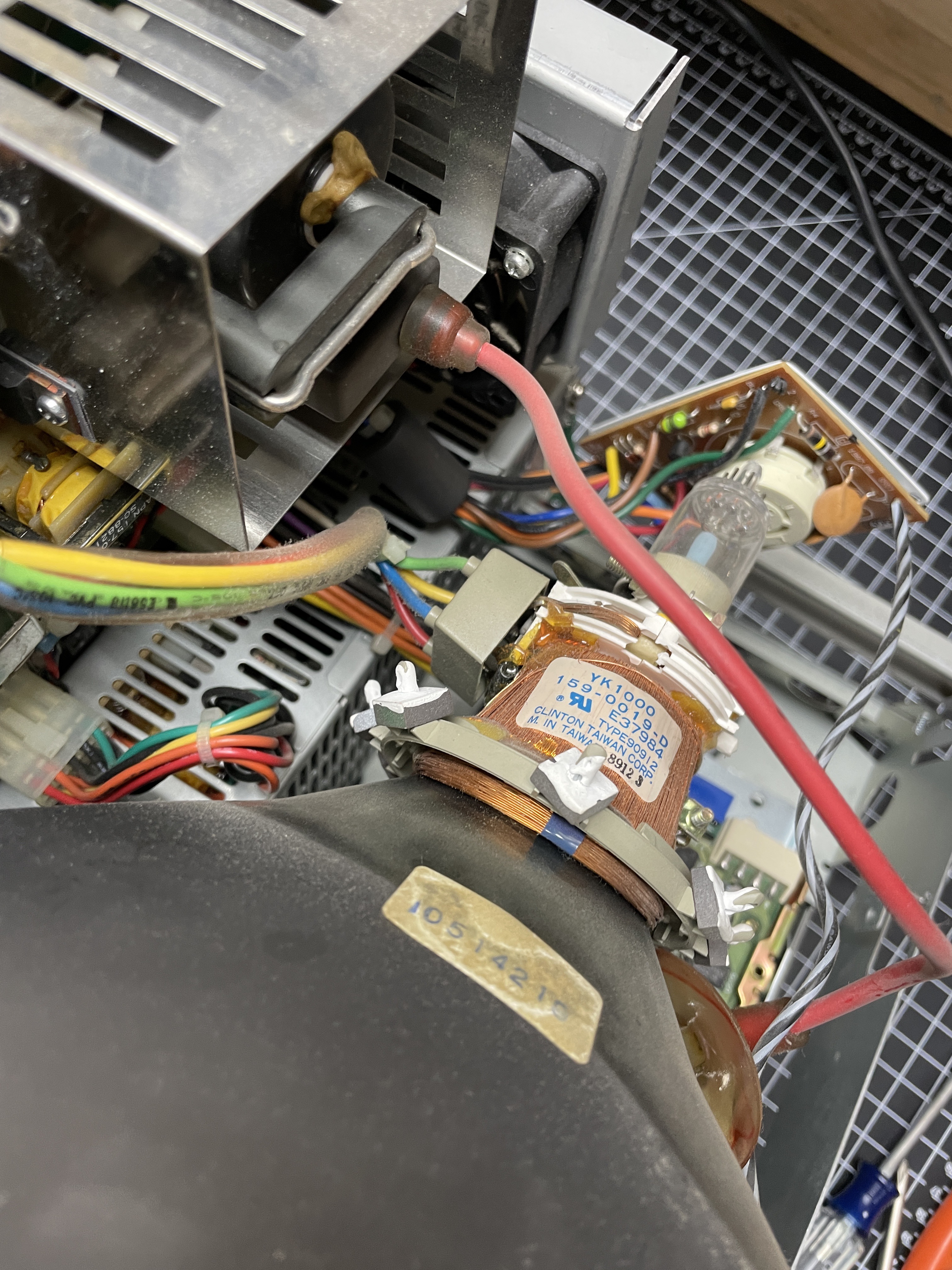
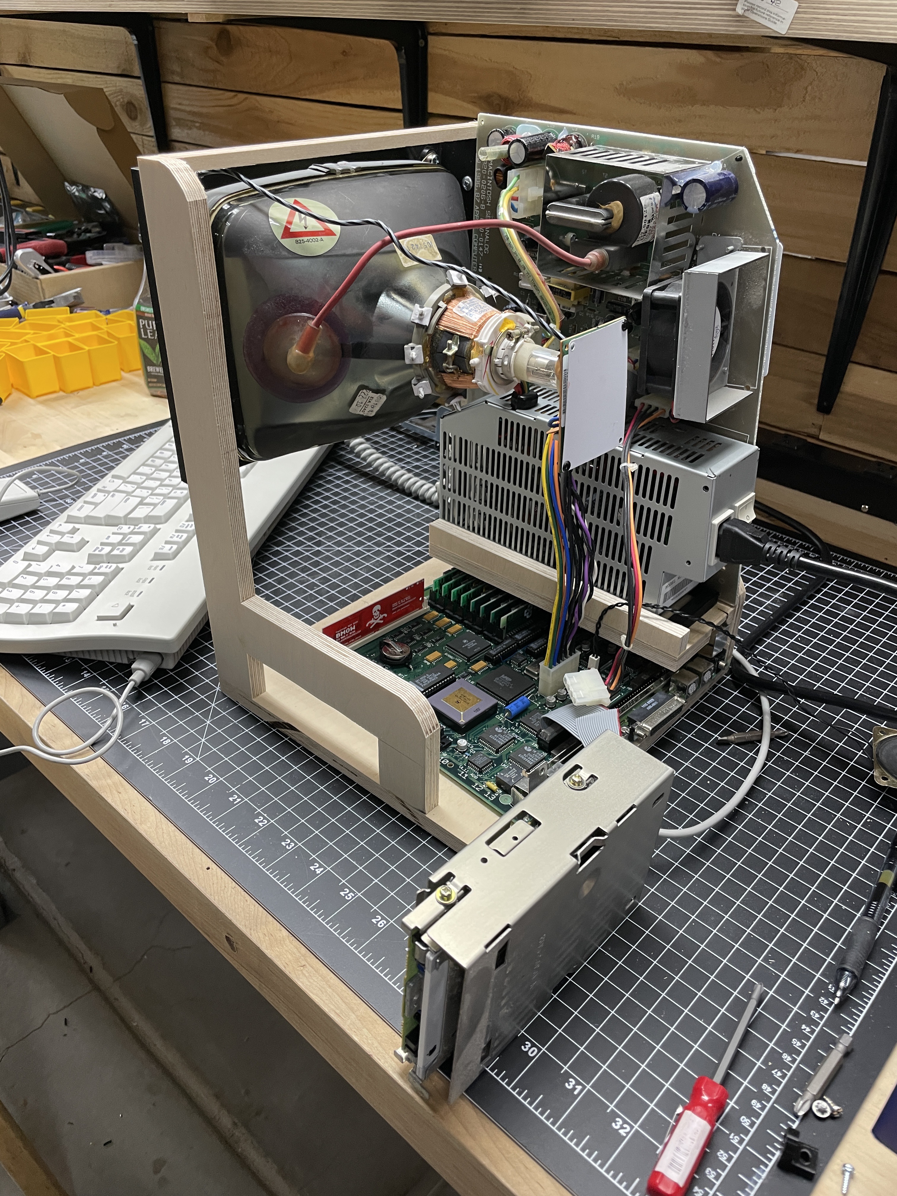
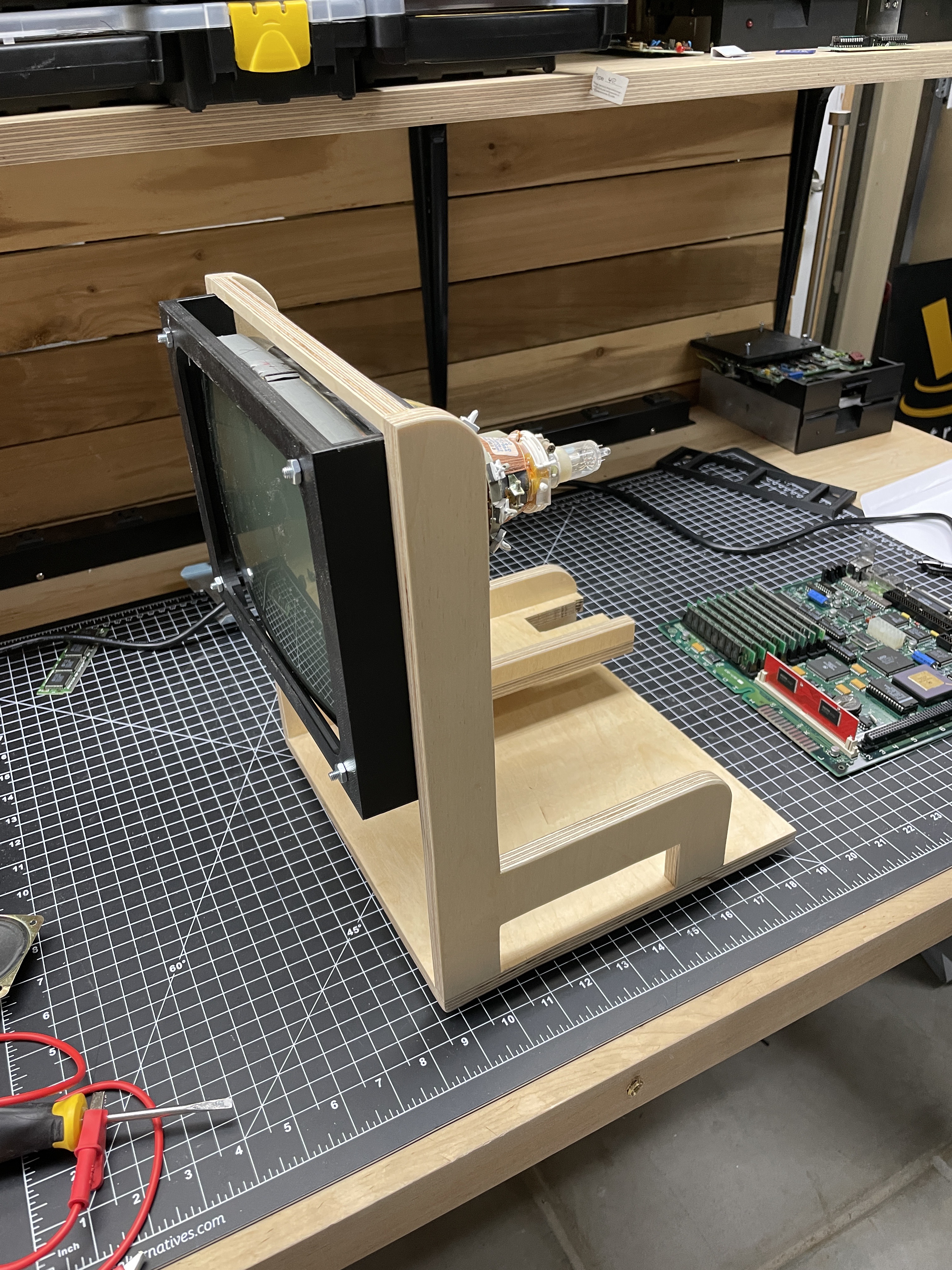
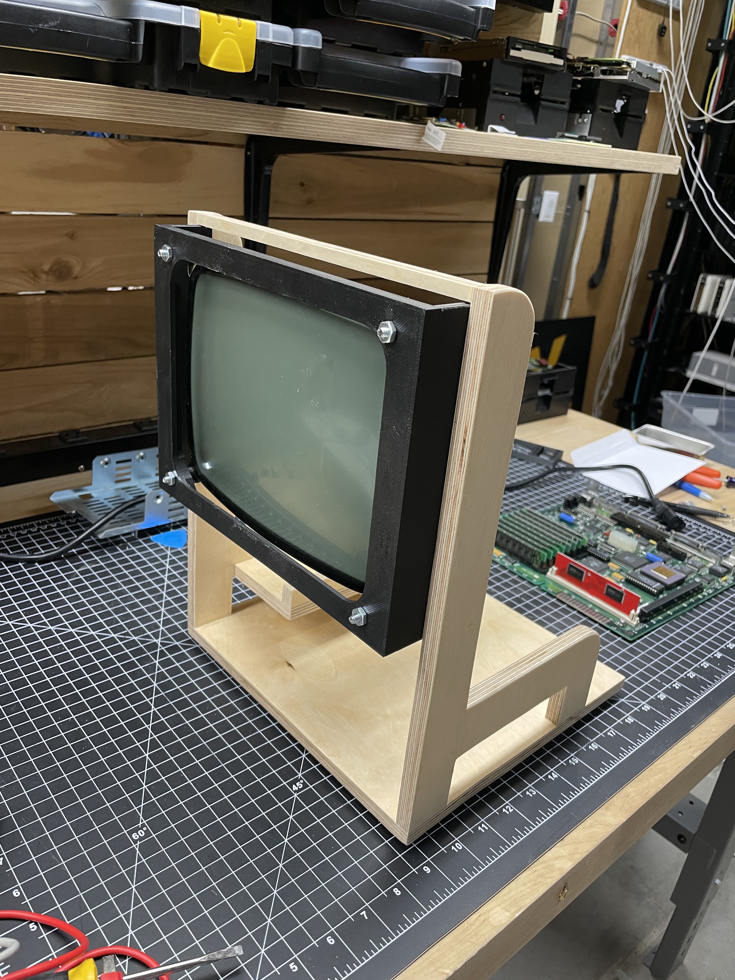
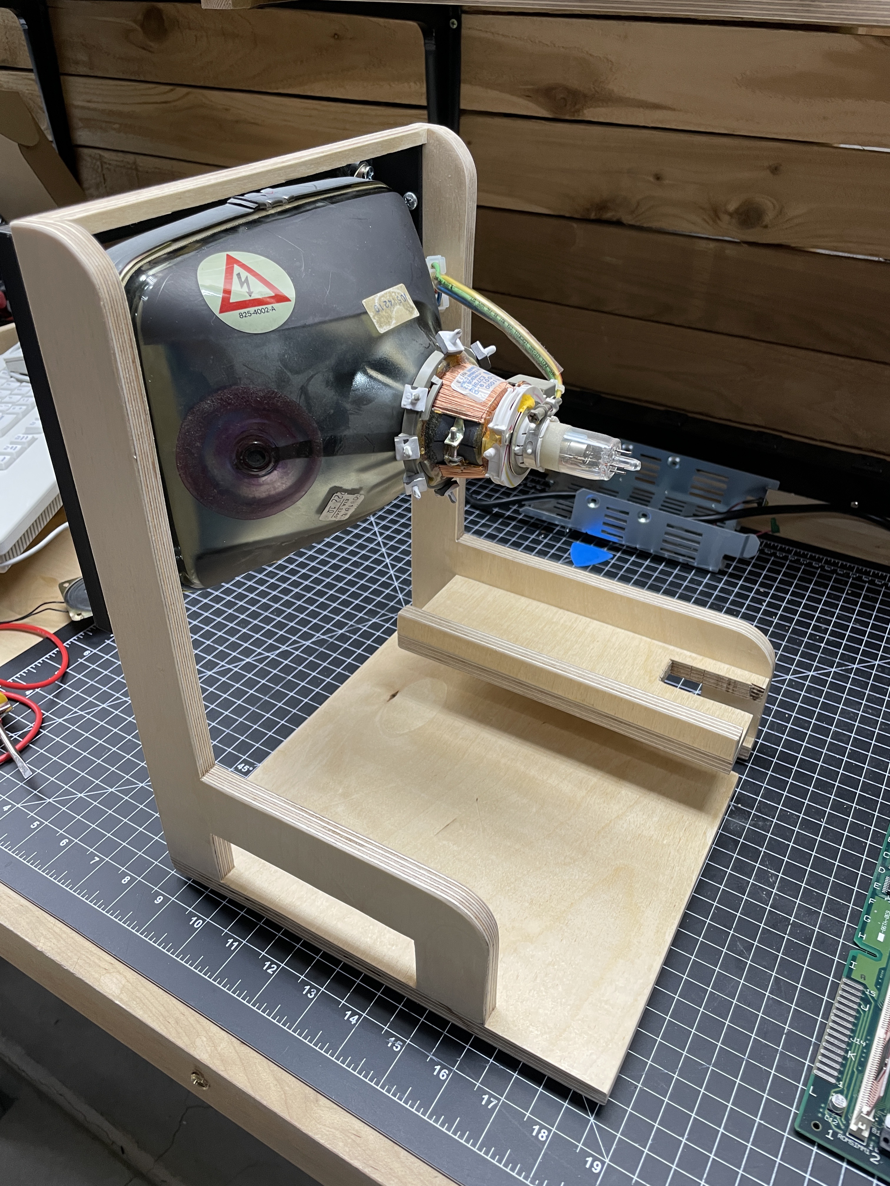
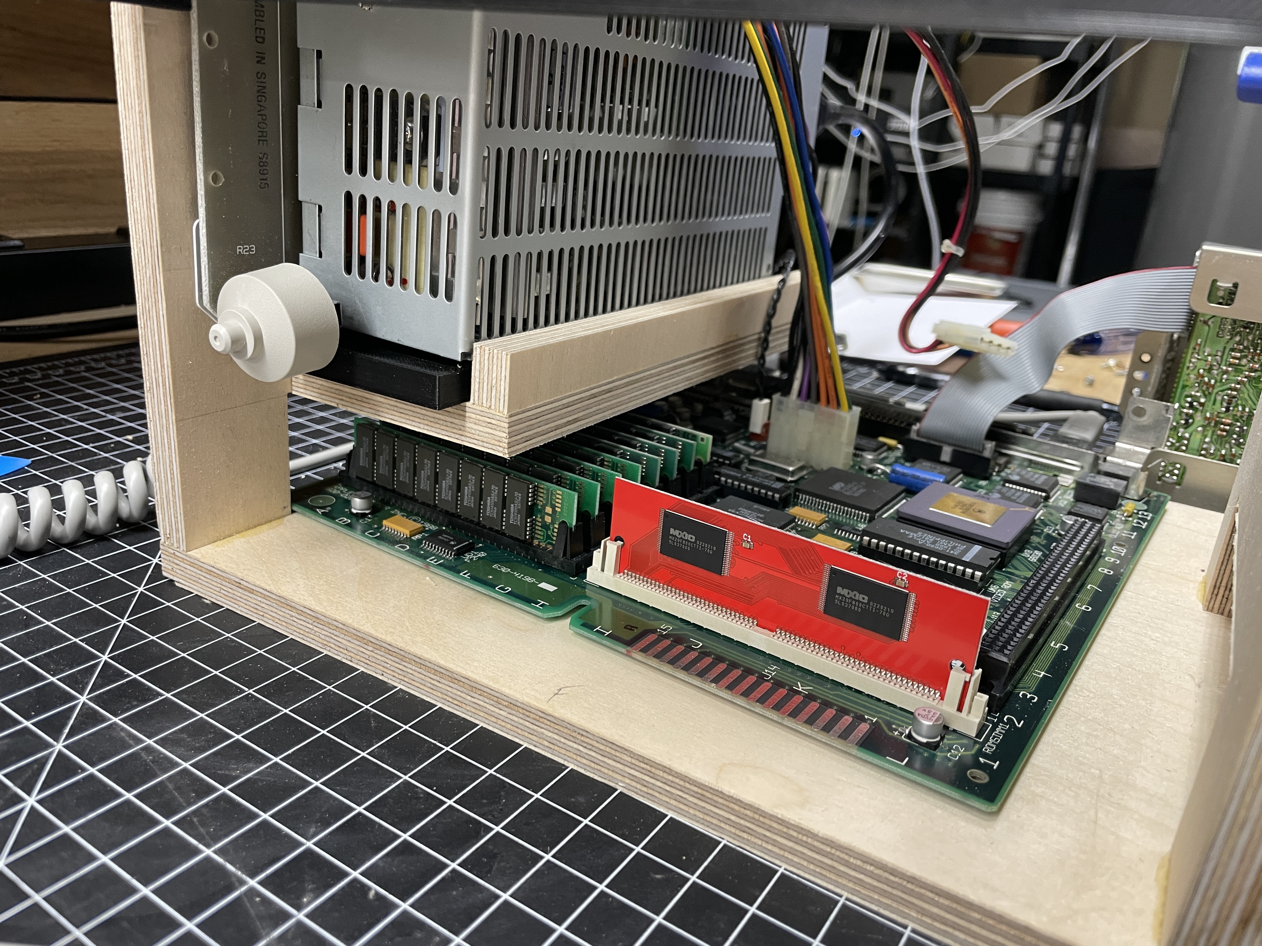
Compact Macs are a pain to work on with the case partially assembled. The CRT anode hangs off to one side, the power supply sits on a little shelf above the logic board, and nothing is accessible from the outside of the shell. To make matters worse, these machines really want to be fully assembled before they will boot reliably, which means every round of debug-and-measure is gated on an assemble-disassemble cycle.
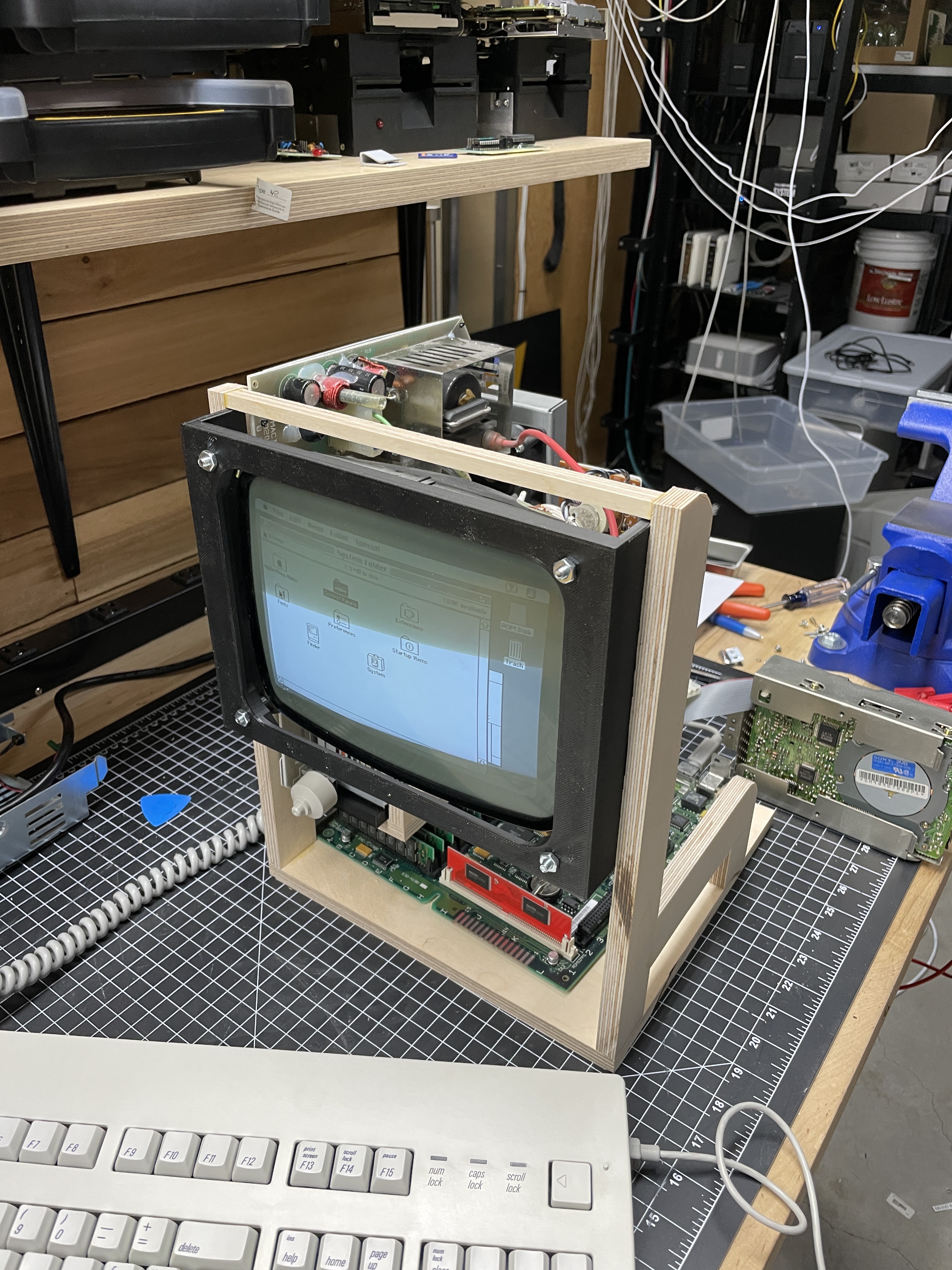
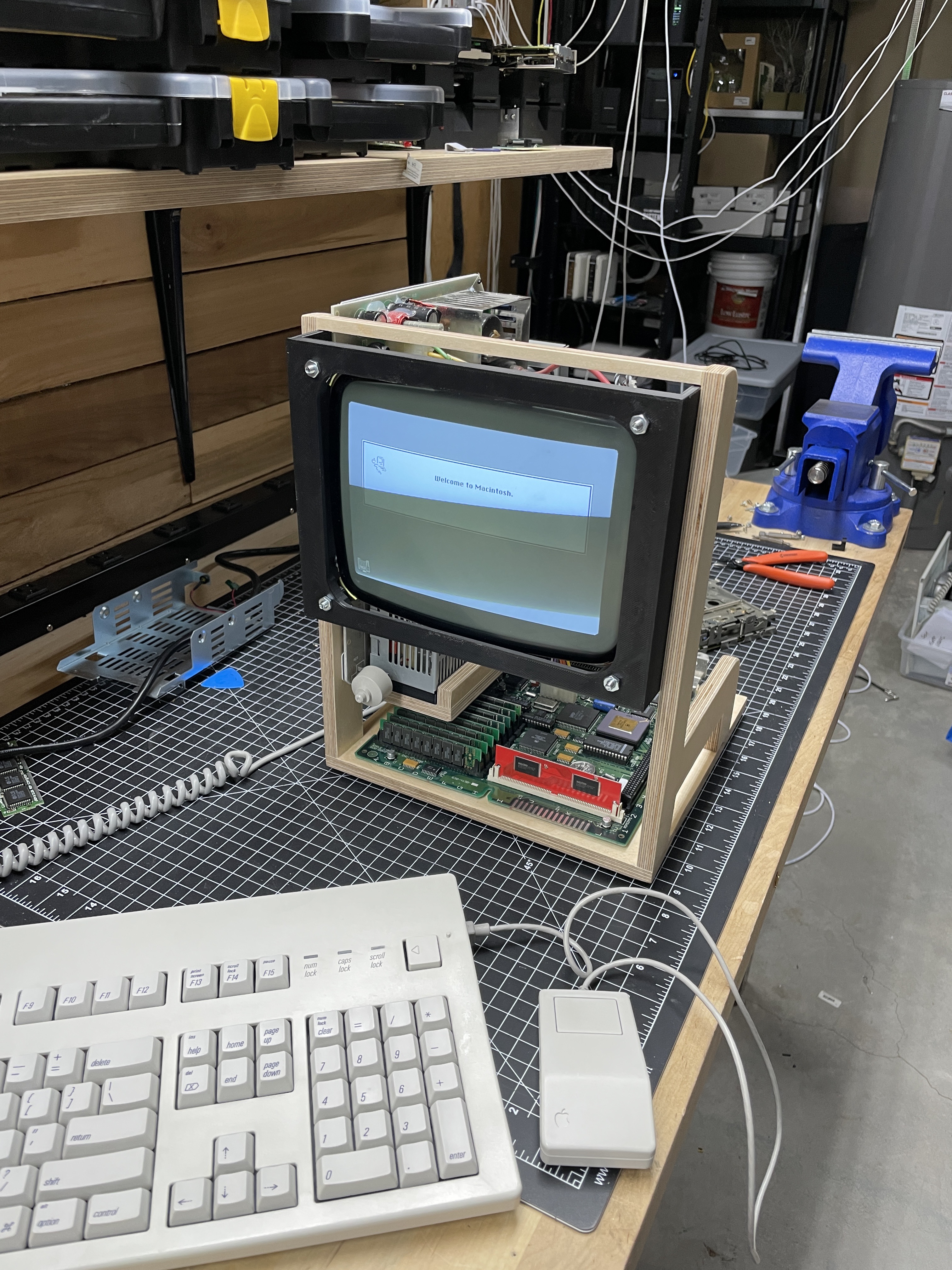
Early in the project I gave up on that and built a plywood service jig. The jig holds the CRT, the analog / PSU board, and the logic board in their correct relative positions, but strips away the plastic shell and the steel chassis. Everything is out in the open: probes fit, cables route cleanly, and power-on to a desktop takes seconds instead of minutes. It has proven invaluable not just on this SE/30 but on every subsequent compact Mac I’ve touched.
The Patient Was Too Far Gone
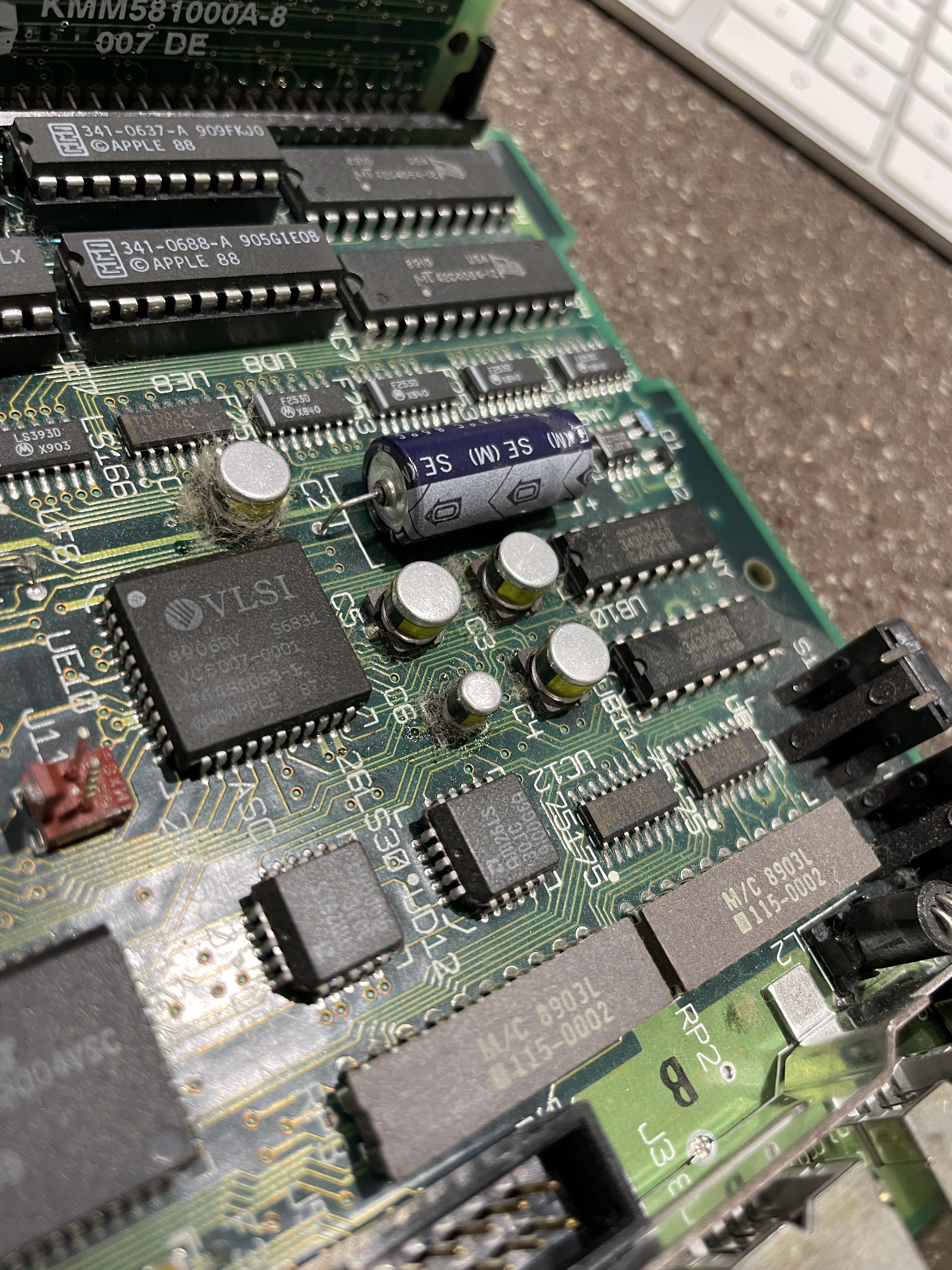
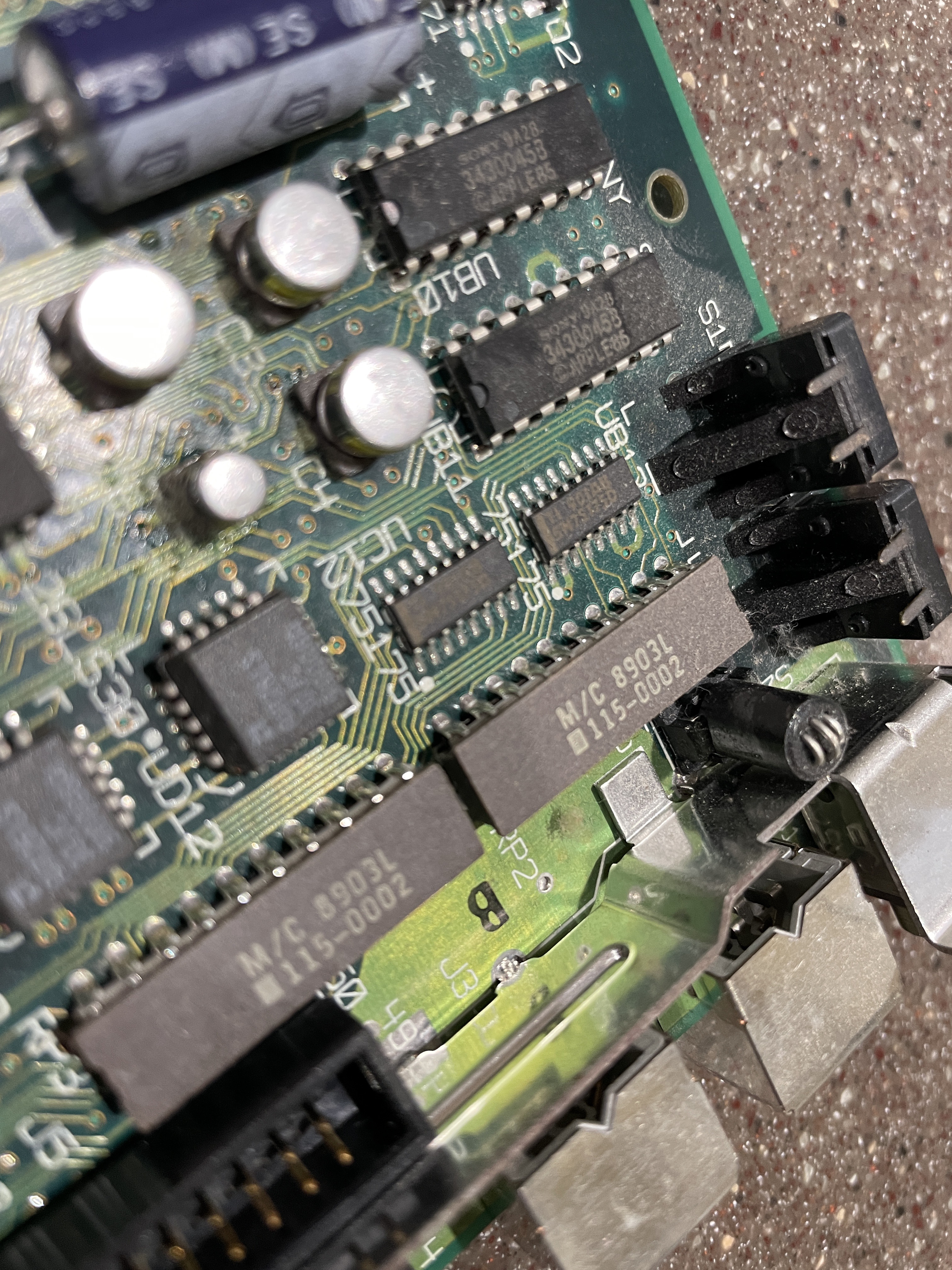
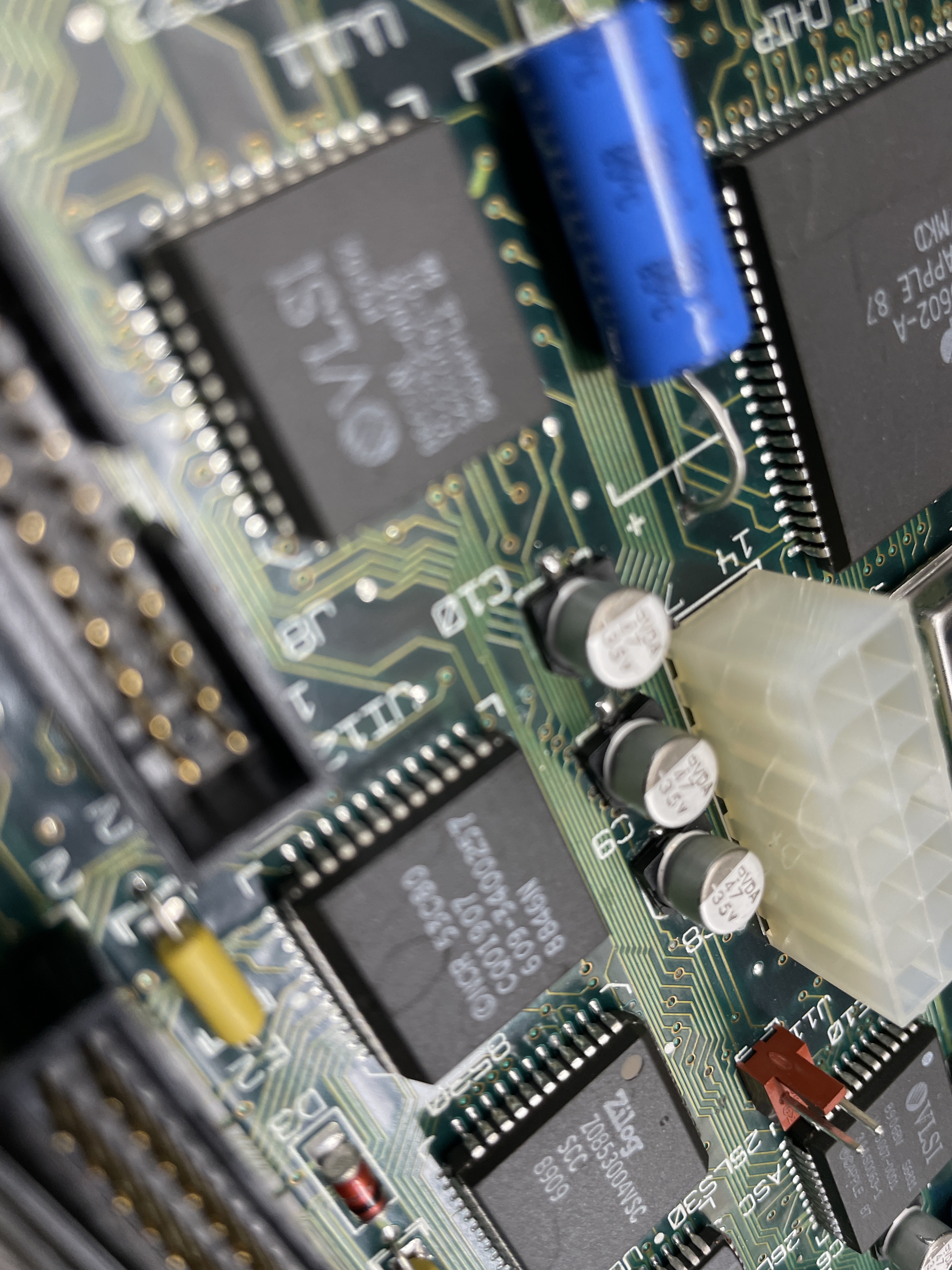
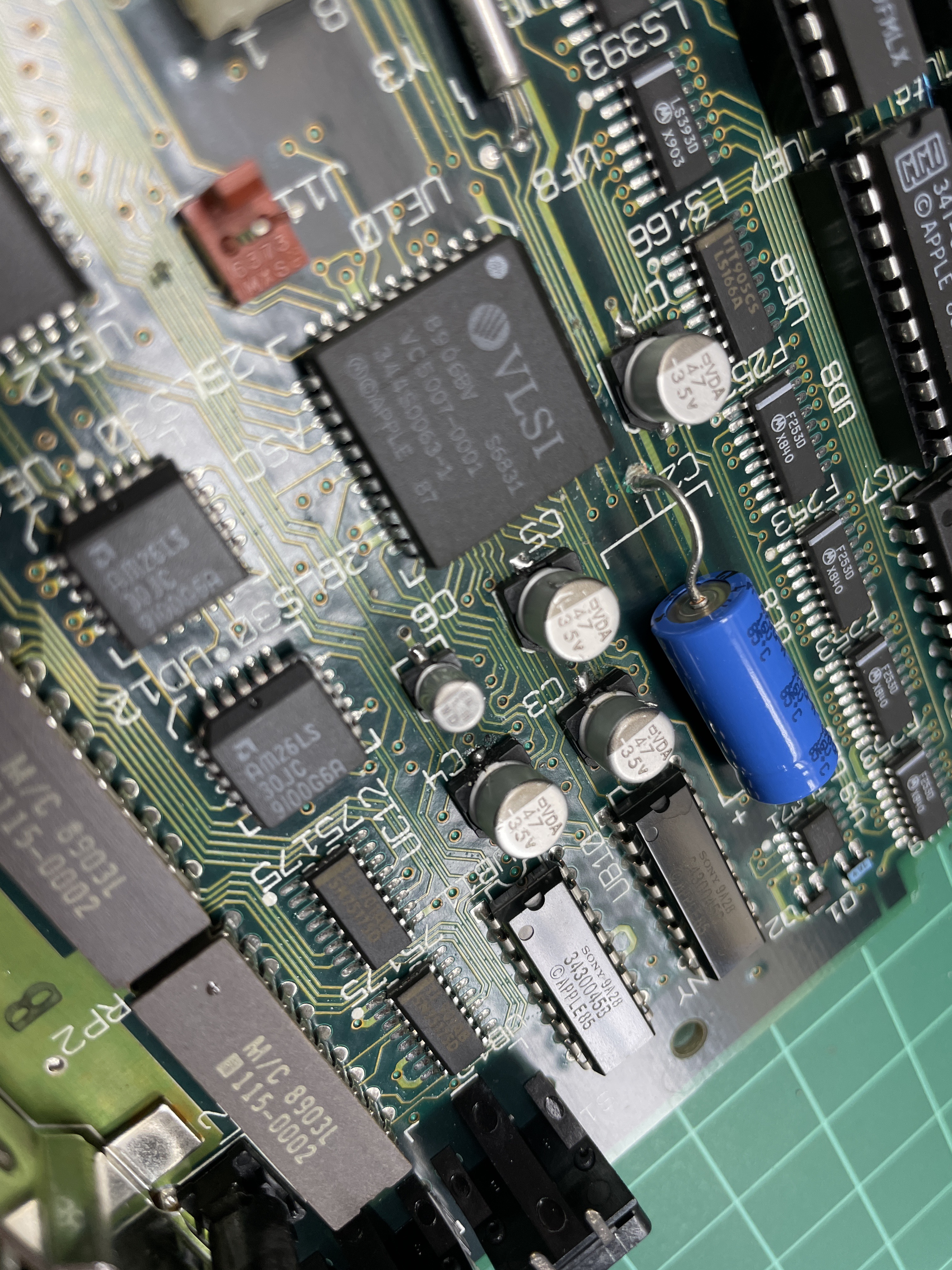
Once the first machine was in the jig and I could see the board properly, the damage became obvious. The electrolytics had indeed leaked, and the leakage had spread across a meaningful portion of the logic board. Worst of all, it had crept under the SCSI controller chip and lifted or eaten several pads and traces in that area.
Still thinking I had a fighting chance, I desoldered the SCSI chip and replaced it. Honestly, at that point in my SMD career I didn’t have the bench skills or the rework tooling to make that repair stick cleanly. The chip came off, the pads didn’t all survive, the bodges piled up, and when I powered the board back up the SCSI bus was as silent as the sound chip. The board was a bust. I set it aside, kept the case and the CRT, and started thinking about Plan B.
A Detour to the Bolle Reproduction Board
At this point I seriously considered going the Bolle reproduction route. Kai Robert Bolle painstakingly recreated the original SE/30 logic board from scratch, stamping out a modern, fresh-off-the-fab PCB that can be populated with new components and used as a drop-in replacement for a hopelessly-damaged original. It is exactly the sort of preservation work this hobby depends on.
I went so far as to order the raw circuit board while I continued to troubleshoot the first machine. In the end, before I committed to populating it myself, another SE/30 turned up on eBay at a fair price and I pulled the trigger on that instead. Practicing SMD rework on the first (dead) board had, perversely, made me measurably better at it, and I had much better luck on the second machine’s recap the second time around.
If you want to read more about the Bolle board project:
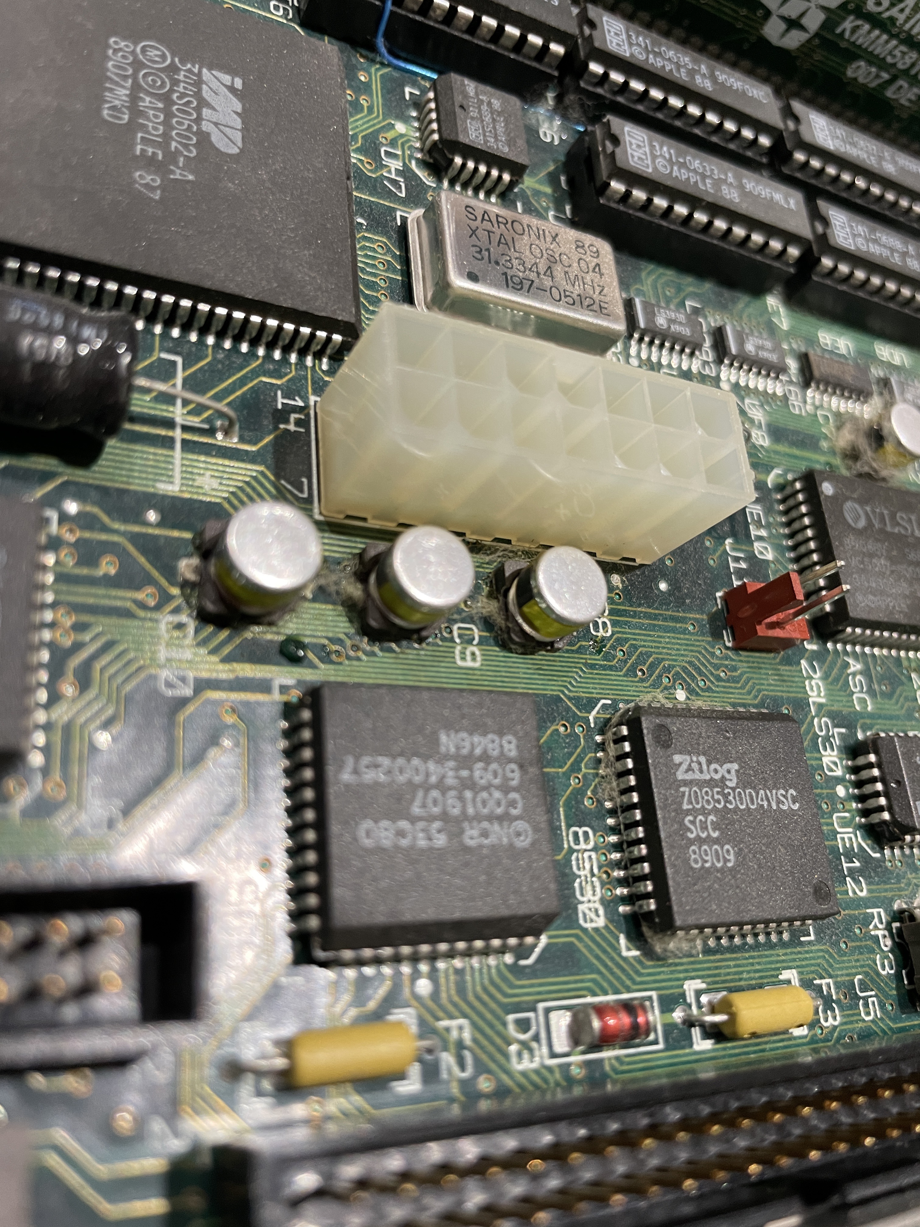
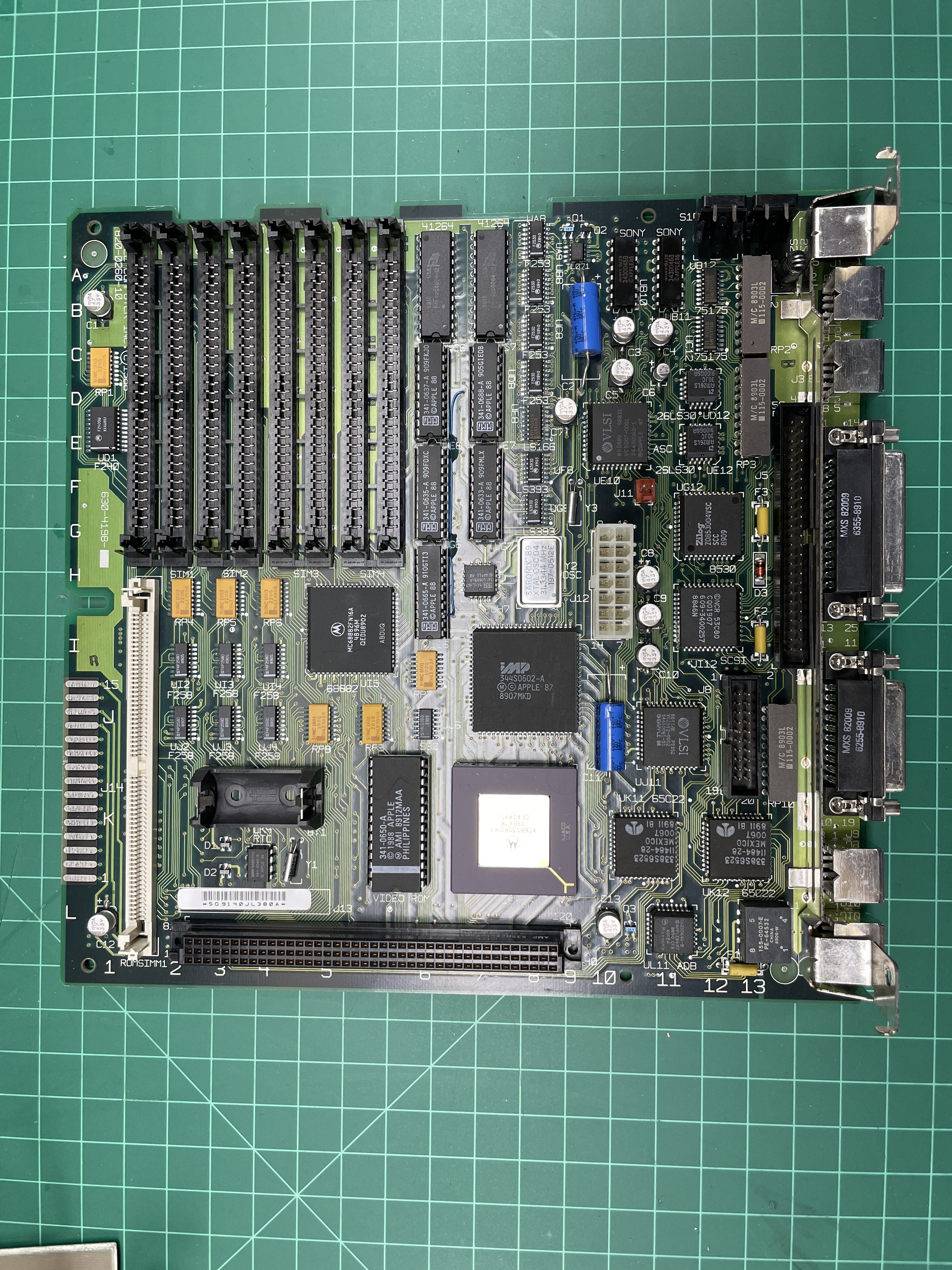
Capacitor Replacement
Every SE/30 needs a recap. If you buy one that has never been serviced but runs, you are living on borrowed time. The telltale early sign is dead or distorted sound — that’s the sound-path caps giving up first. Keep using the machine past that point and the filter caps on the power rails will follow, and the leakage will start attacking traces.
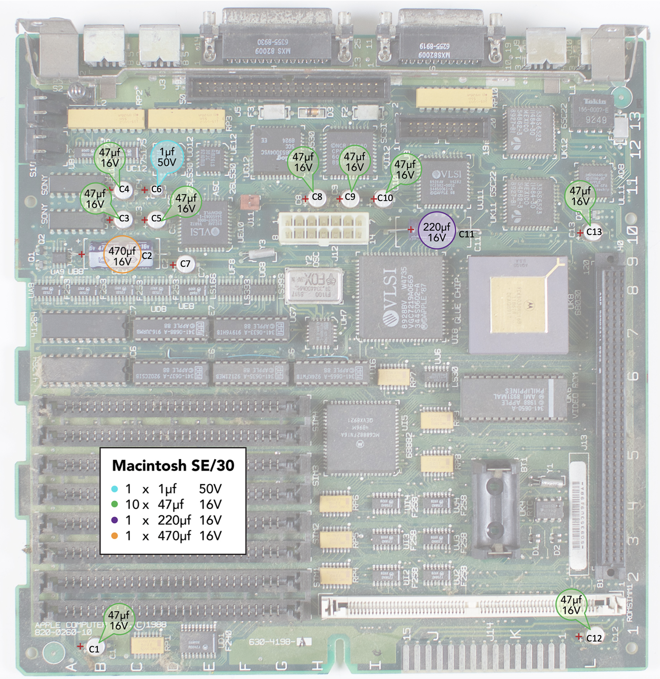
On the logic board there are twelve electrolytics to replace:
| Ref | Function |
|---|---|
| C1 | +5V filter |
| C2 | +12V filter |
| C3 | SND-L-DC (sound) |
| C4 | SND-R-DC (sound) |
| C5 | VREF (sound) |
| C6 | SND-R-A/D (sound) |
| C8 | -5V filter |
| C9 | -12V filter |
| C11 | +5V filter |
| C12 | +12V filter (sound) |
| C13 | +5V filter |
| C24 | SND-L-A/D (sound) |
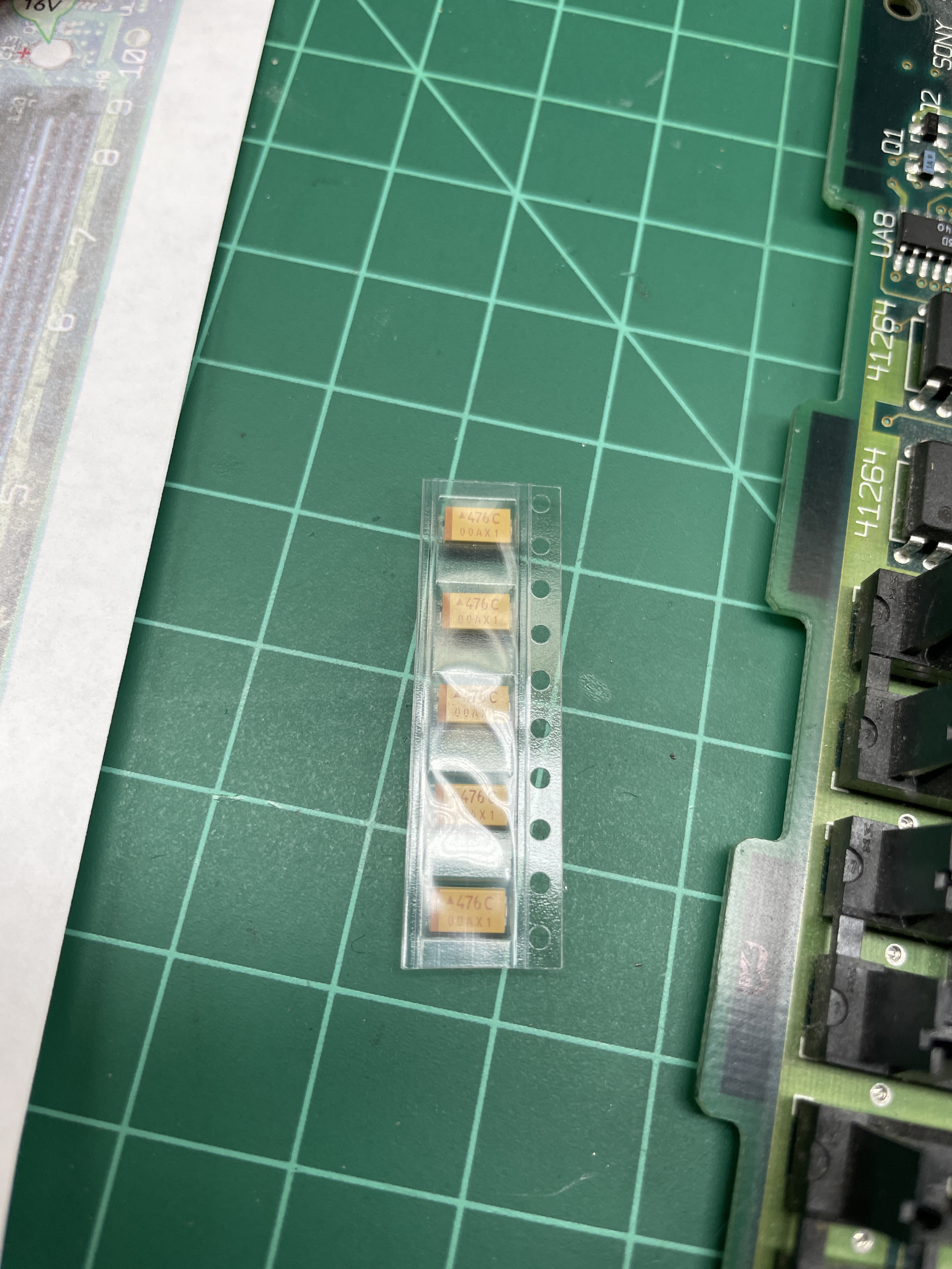
Most of them are 47 µF 16V. There is one 1 µF 50V, one 220 µF 16V, and one 470 µF 16V. Here is a diagram I put together showing where each cap sits on the board and what part of the machine it services:
There are sellers on eBay that will ship you the complete set pre-matched for an SE/30. I replaced the electrolytics with tantalums of the same value, which is now the common modern approach — tantalums don’t leak and don’t dry out the way electrolytics do.
A few practical notes from doing this twice:
- Use low-temperature paste solder. It flows well, wets the pads cleanly, and keeps you from overheating the nearby traces.
- Remove the old caps carefully with a hot-air rework station, not a soldering iron. Rocking a leaking cap off a corroded pad with a stick iron is the single most common way to tear a pad off an SE/30 board.
- Once the old caps are off, clean every pad. Isopropyl and a toothbrush, then isopropyl and a cotton swab. Residual electrolyte will attack traces under your fresh solder joint if you leave it.
- Tin each pad with a tiny dot of paste solder. Place the new cap. Heat each end until the solder flows, then pull the heat off.
- If a pad is gone, run a bodge wire from the nearest surviving point on the trace to where the cap leg needs to go.
Watch a couple of YouTube videos before your first attempt. The technique is not hard once you’ve seen it done, but the consequences of getting it wrong on an SE/30 board are painful.
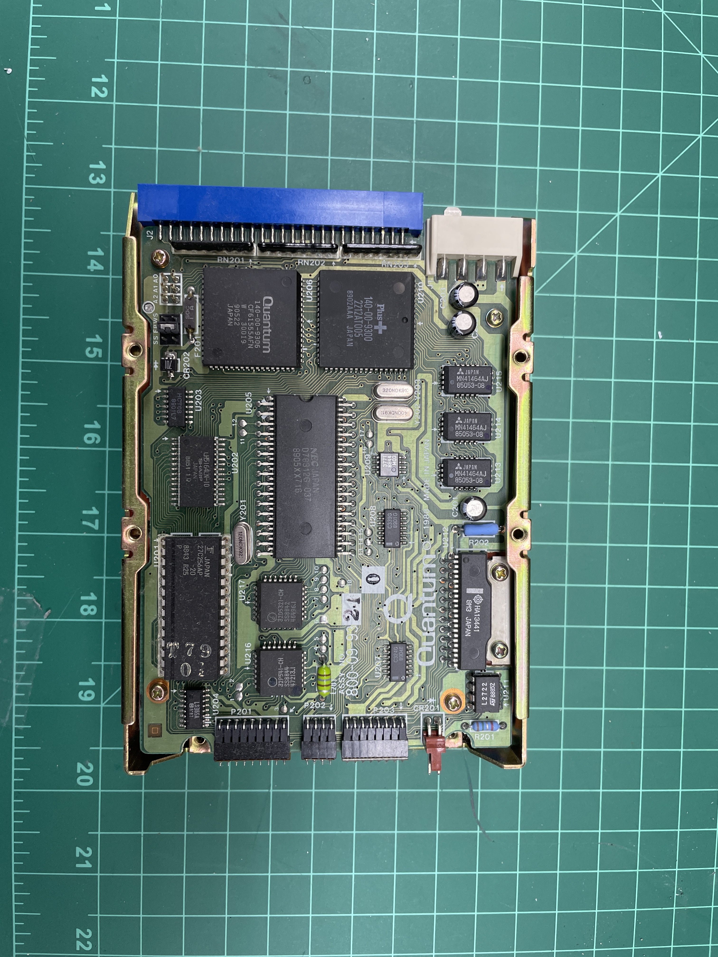
Storage: ZuluSCSI 2040
I swapped the original mechanical SCSI hard disk for a ZuluSCSI 2040. ZuluSCSI is what I use across the workstation collection, so using it on the SE/30 meant one less variable and a known-good tool set.
BlueSCSI is the other well-loved option in the compact Mac community, and there is no wrong choice between the two. I went with Zulu purely out of familiarity.
This particular SE/30 shipped with a card in the PDS slot that was wired up for a Radius display I did not have. Rather than tearing that card out, I designed and 3D-printed a bracket that does two things: it mounts the ZuluSCSI 2040 in place of the original hard disk, and it extends an SD-card slot out through the exterior of the machine where the Radius card’s display connector would normally have exited. A short micro-to-full-size SD extender cable connects the Zulu board to the external slot, so I can pull, image, or swap the SD card without opening the machine up. This is the same pattern I’ve used on other workstations in the collection — disk images want to be editable from outside the case.
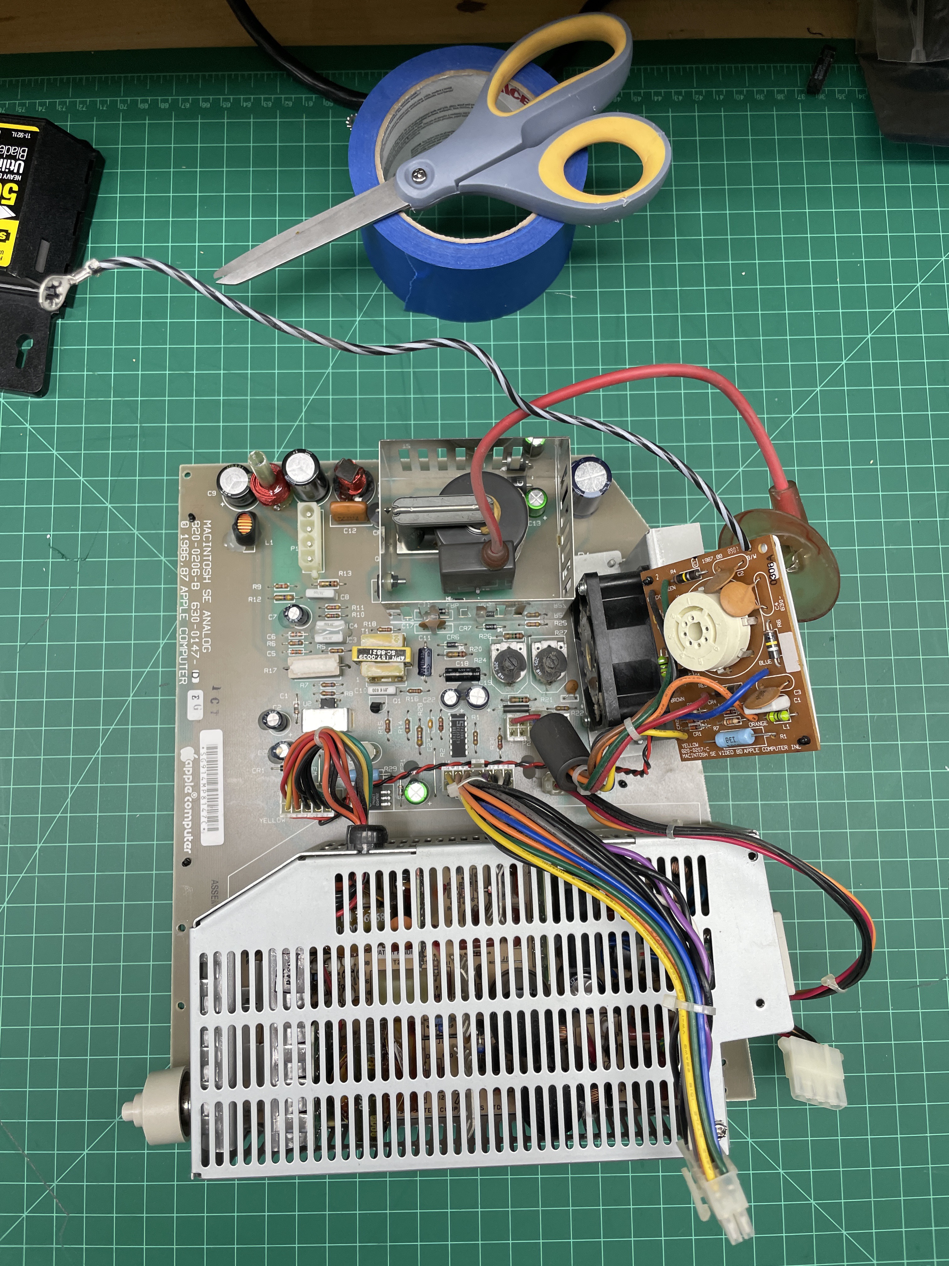
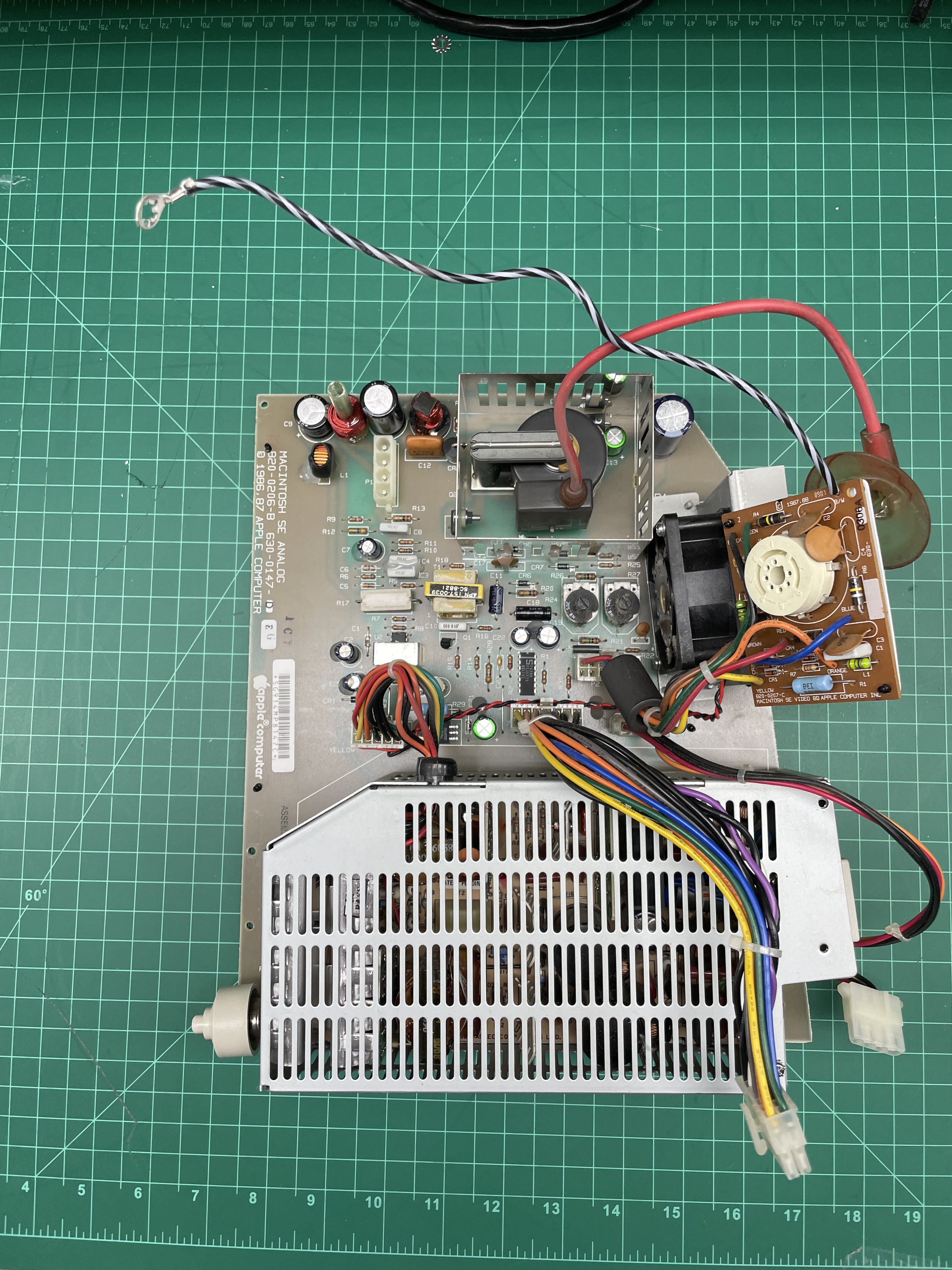
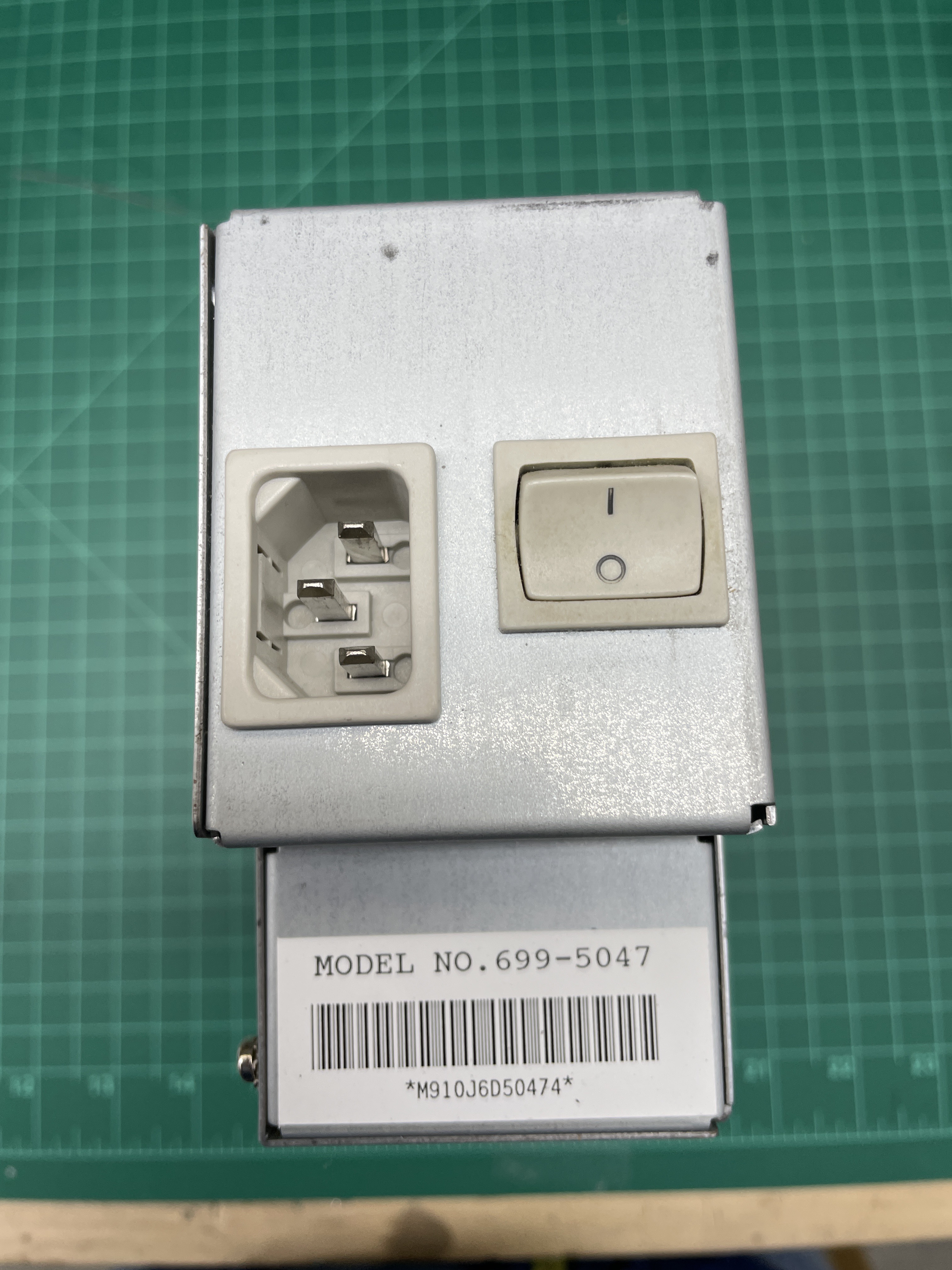
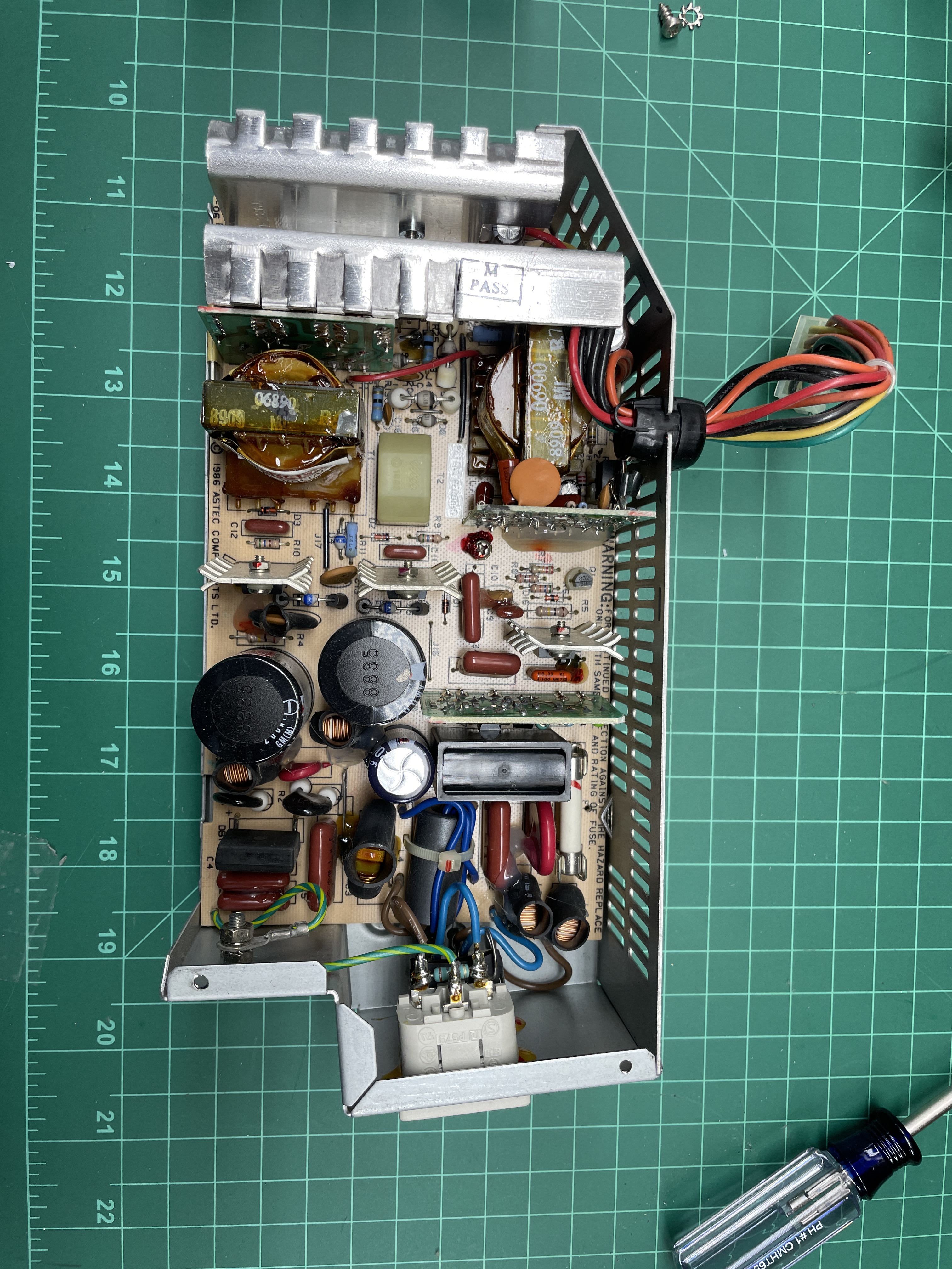
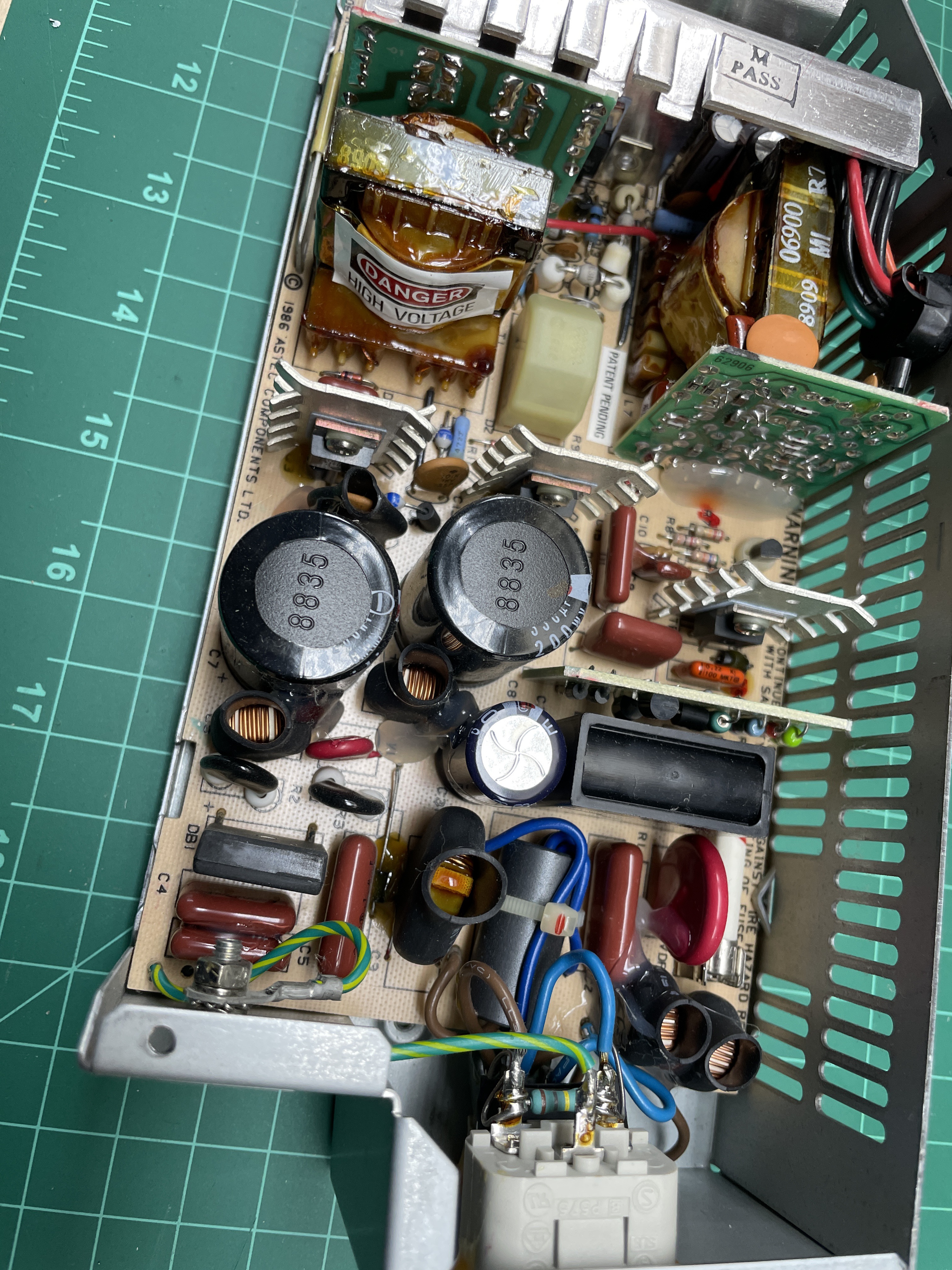
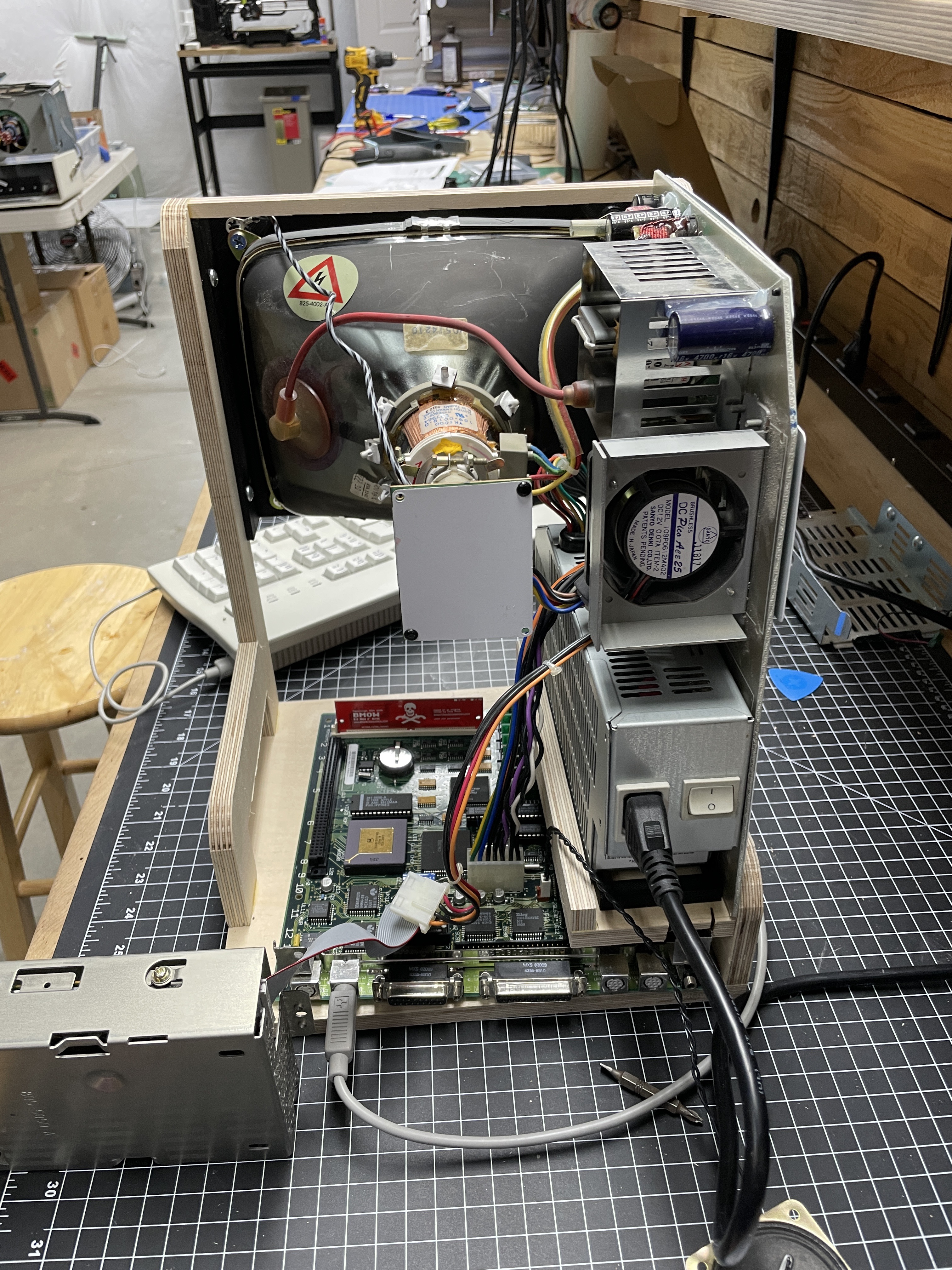
A Brand-New Power Supply
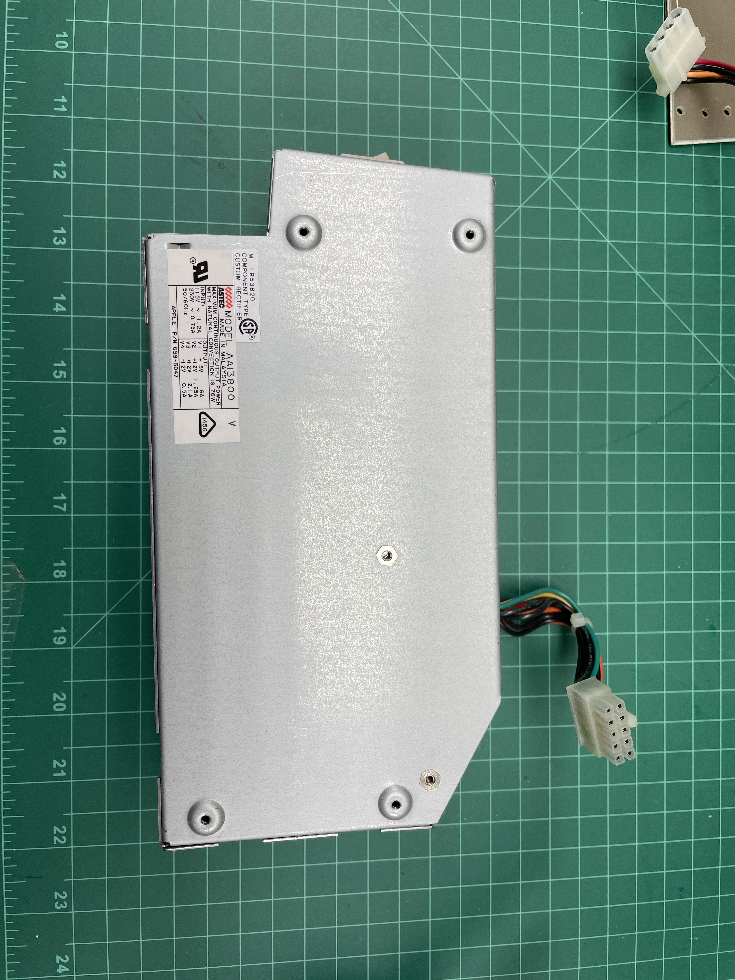
Right as I was working through this restoration, someone in the community released a completely new power supply replacement for the SE/30, designed as a drop-in for the original Astec and Sony supplies. I bought one and used it in place of the original PSU from the second machine.
The original SE/30 power supply is a finely-tuned piece of late-80s switch-mode engineering that also happens to share the same capacitor-aging problem as the logic board. A dead or dying SE/30 PSU will take a logic board with it on its way out, which makes it worth replacing preemptively on any machine you plan to use for years.
Between a fresh set of tantalums on the logic board and a brand-new power supply, this SE/30 should last a very long time. The CRT is the only component of original vintage still in the analog signal path, and CRTs generally outlast their supporting electronics if they are driven by a clean supply. For reference, here’s the video that prompted the PSU purchase:
What Happened to the First Machine
The case, CRT, and front bezel from the first (dead) SE/30 were still perfectly good. Throwing any of that into a landfill felt wrong, and it sat on a shelf for a few weeks while I thought about it. Eventually that leftover hardware became the foundation for a completely separate project: a reimagined SE/30 that runs Mini vMac on a Raspberry Pi behind a modern LCD, sharing only the original beige plastic with its fully-restored sibling.
You can read about that build here:
- Macintosh SE/30 Reimagined - The emulator build that grew out of the first dead SE/30’s bones.
Conclusion

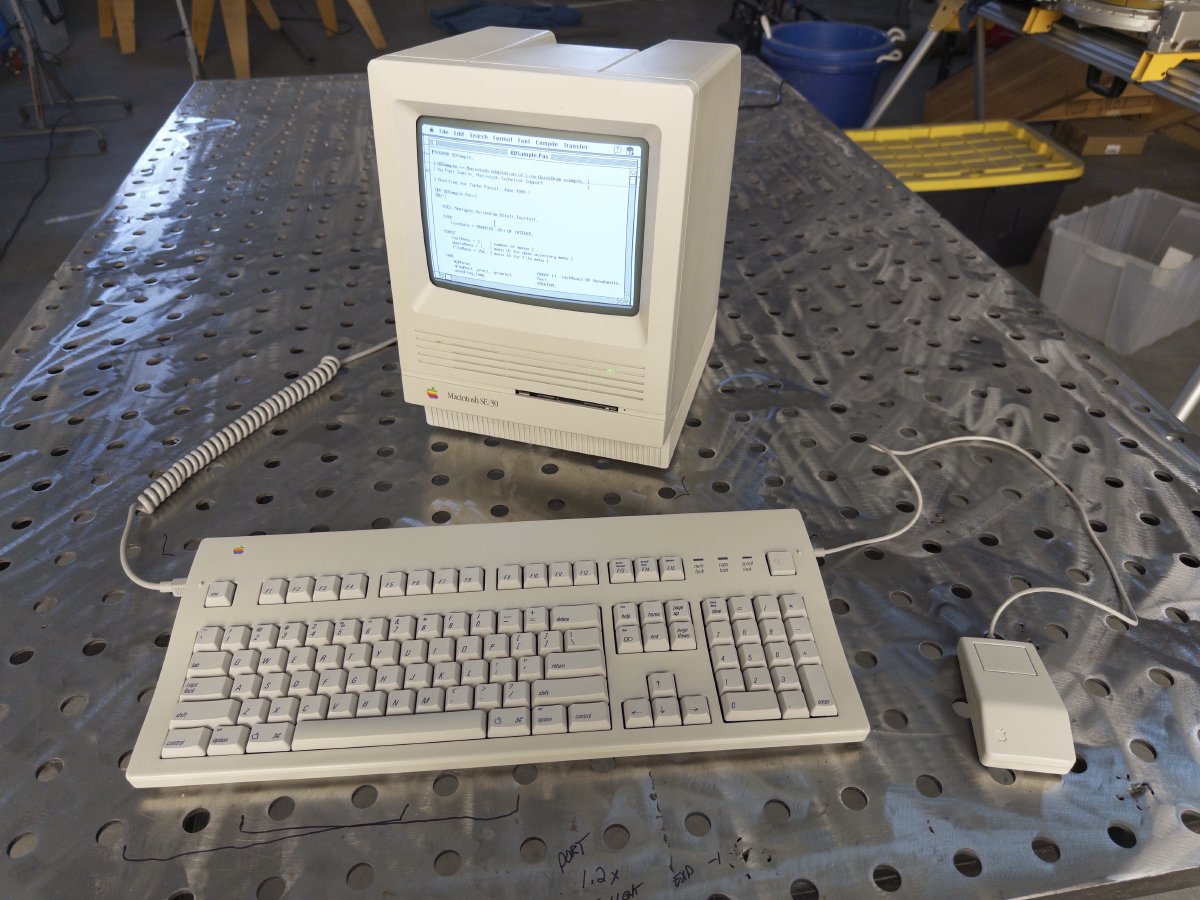
I’m glad I ended up with a working, and reasonably future-proof, SE/30. It was one of the more difficult restorations in the collection — two machines in, one SCSI chip replaced badly, one Bolle board ordered and not used, a full recap, a new PSU, a 3D-printed Zulu bracket, and a plywood jig I’ll keep using for years.
After this machine and the Macintosh Color Classic, I decided I’m pretty much done with Macs. They are genuinely harder to restore than the equivalent-era workstations, the caps problem is ubiquitous, and when you are done you have a comparatively slow machine with a small black-and-white screen. When I get the urge to use a classic Mac now, I tend to reach for the reimagined SE/30 — it’s faster, lighter, has a color screen, and doesn’t make me feel guilty every time I power it on.
The original SE/30 still sits on the shelf next to it, though. It is the machine I did the most work on, and it has earned its spot.
Related Articles and Links
Macintosh SE/30 Reimagined - The emulator build that reuses the case, CRT, and front bezel from the first dead SE/30.
Macintosh Color Classic - The other late-era compact Mac in the collection.
Bolle’s SE/30 Reproduction Board - Kai Robert Bolle’s recreation of the original SE/30 logic board, a potential rescue for boards too far gone to repair.
Replacement SE/30 PSU (YouTube) - The video that prompted the new power supply purchase.
ZuluSCSI Overview - Overview of the ZuluSCSI boards used throughout the collection.
ZuluSCSI Disk Images - Setup and configuration of ZuluSCSI disk images for vintage systems.
Gallery