A short history of Commodore
Commodore started life in the 1950s selling typewriters, then adding machines, then calculators. By the mid-1970s Texas Instruments was eating the calculator business alive by controlling the chips and squeezing every competitor’s margins to nothing. Jack Tramiel, Commodore’s founder, watched the squeeze and concluded that the only way out was to own the silicon. So in 1976 Commodore bought MOS Technology, the small Pennsylvania fab where Chuck Peddle had designed the 6502, in an all-stock deal that gave MOS shareholders roughly 9% of Commodore. Peddle came along with the deal. That acquisition is the single decision that made everything that followed possible.
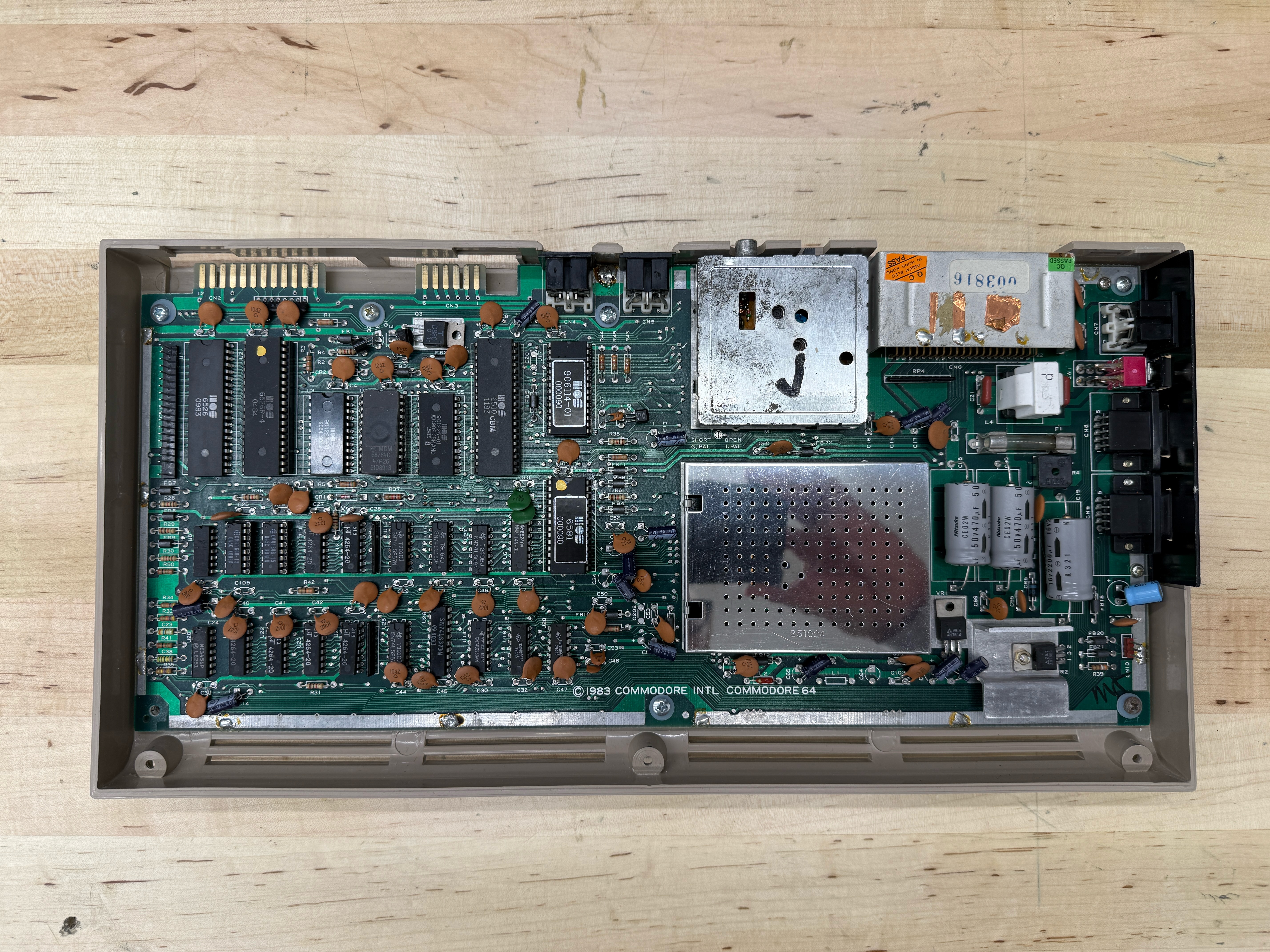
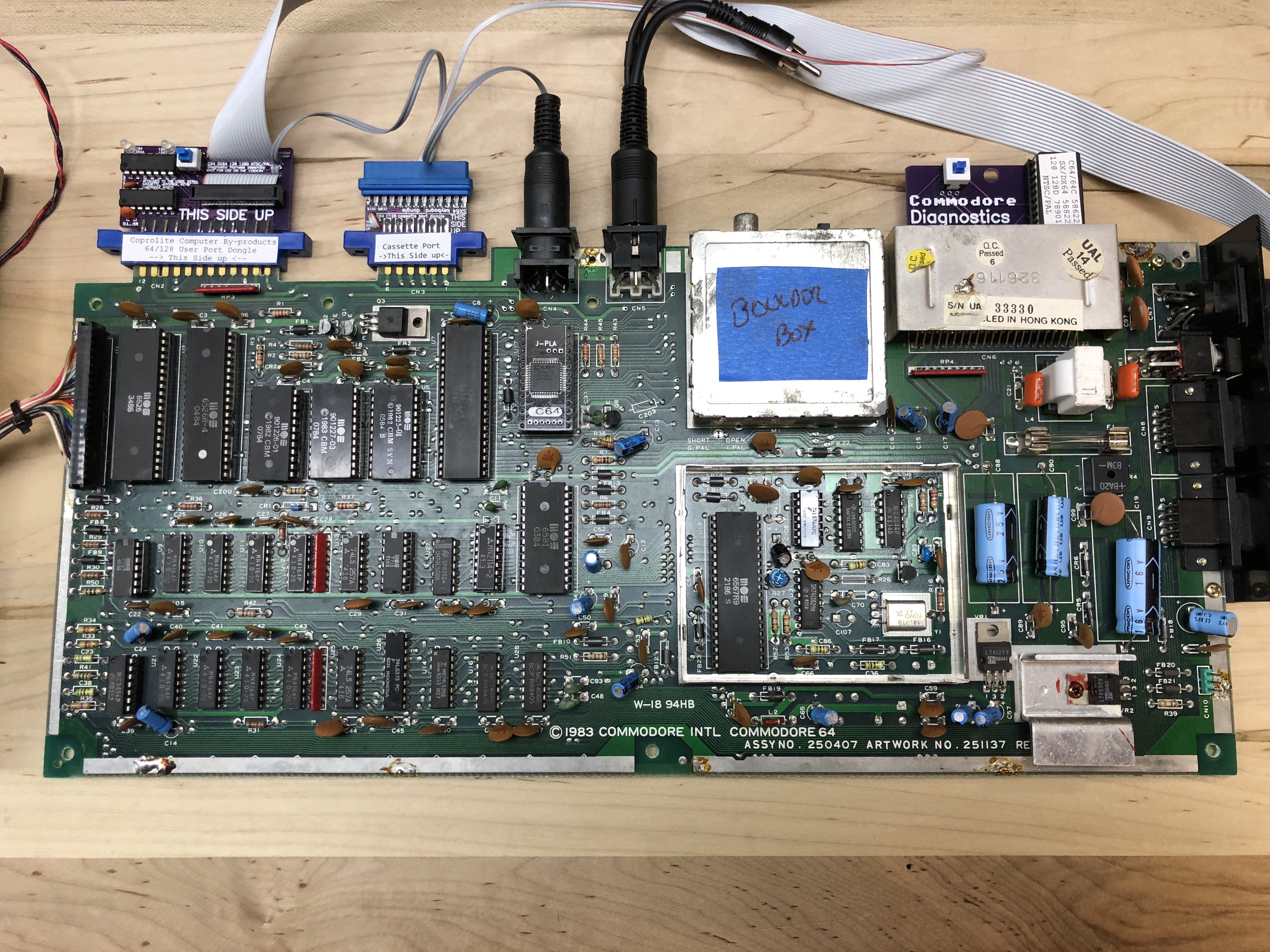
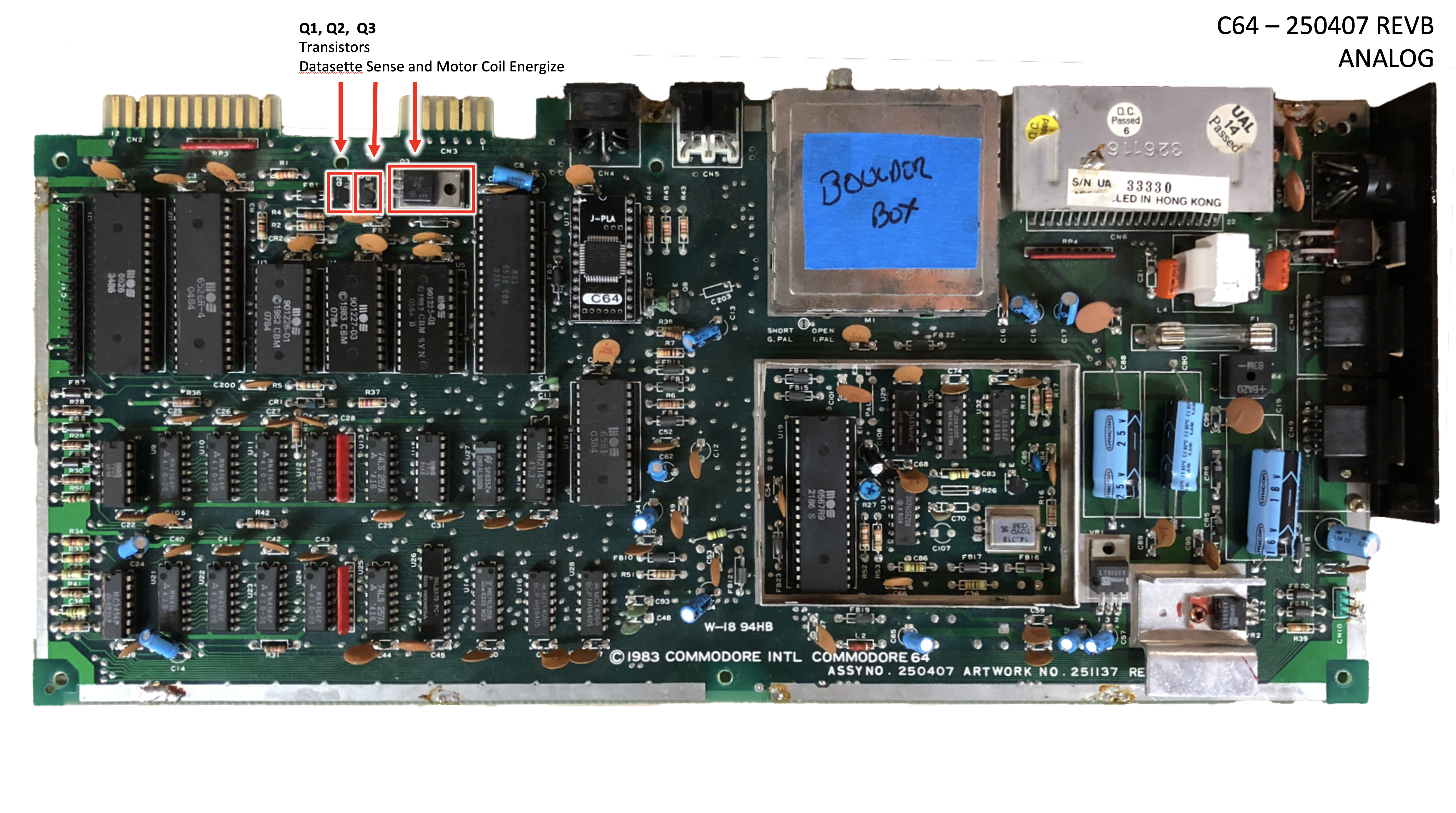
In 1982 it produced the Commodore 64: a 6510 CPU, a 6581 SID, a 6567 VIC-II, two 6526 CIAs, and a 906114-01 PLA, all designed by MOS for Commodore and built nowhere else. The motherboard above is that bill of materials, in physical silicon. Custom chips at retail were unprecedented for a sub-$600 machine. The SID had real analog filters on a 1982 home computer. The VIC-II did sprites and raster effects no other consumer chip could match. None of those parts existed in anyone else’s catalog. None could be second-sourced. And because Commodore owned the fab, it could ship the C64 at $595 in 1982, drop it under $200 within two years, and still make money on every unit.
That pricing destroyed TI’s home-computer division (which exited the market in 1983) and gutted Atari’s 8-bit line. The C64 went on to sell somewhere between twelve and seventeen million units. It’s the best-selling single home computer of the 1980s, and Guinness’s record-holder for “best-selling desktop computer model.”
Which is why, forty years later, when one of those chips dies, you’re not just buying a replacement. You’re sourcing silicon from a fab that no longer exists, originally made by a company Commodore bought to keep alive. You’re trying to find it on eBay at an ever-increasing price.
My first computer
I was not a great high school student. The computer lab at my school was reserved for the advanced math track, and I wasn’t in it. So the kid who would later spend his career writing software was, at seventeen, locked out of the only computers in the building.
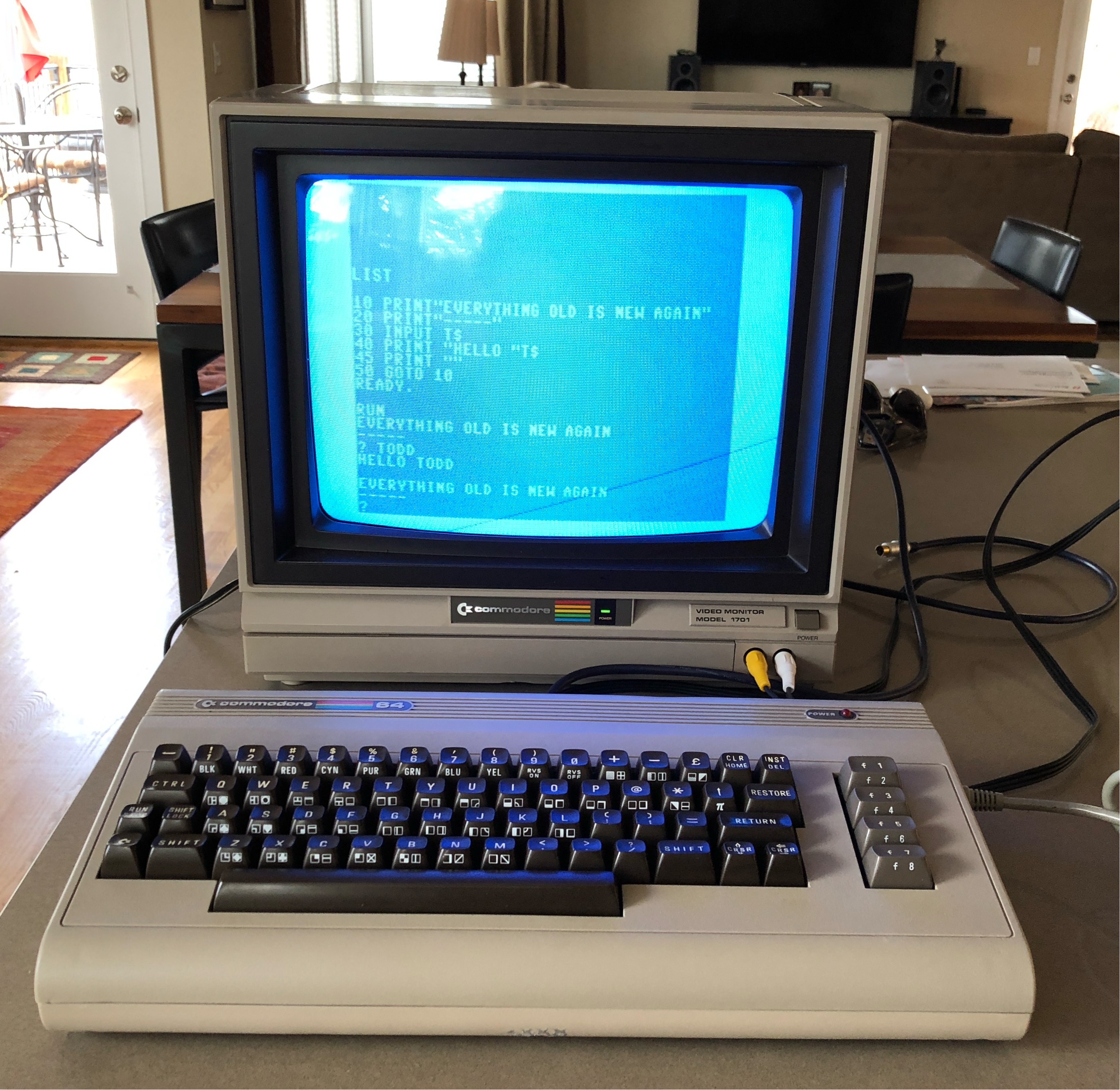
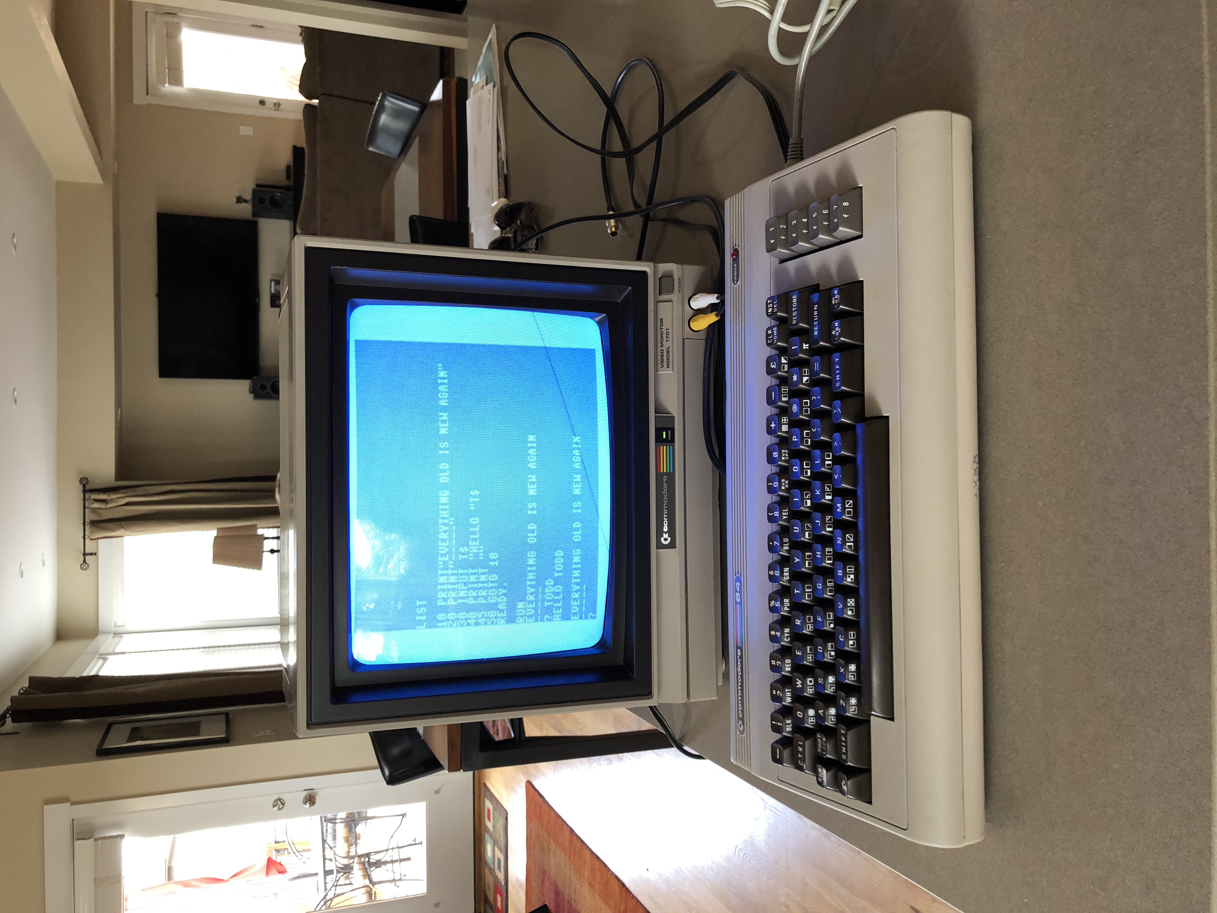
The C64 changed that. I got mine in college, my first computer, period. I taught myself BASIC on it, then Blitz! BASIC, a proper compiler that turned interpreted BASIC into fast P-code under a tiny runtime. Alongside that I picked up 6510 assembly, partly out of curiosity and partly because the C64 made it unusually approachable for a 1980s home machine.
That assembly grounding got me in the door at NASA Dryden a few years later, on the X-29 flight-test program. It was concepts more than any specific instruction set: I wasn’t writing the flight code, and the X-29’s flight computer was a proprietary Honeywell, not a 6510. I was testing it, and reading the disassembly was central to the job. The path from “kid who wasn’t allowed in the computer lab” to “helping test flight software for an experimental aircraft” went directly through the keyboard of this machine.
The C64 was also a temperamental machine. About every few months mine would do something unforgivable: a blank screen, garbage on boot, a key that stopped working. I’d ship it back to be exchanged. Commodore’s repair channel at the time was basically a roulette: send in your broken box, get someone else’s repaired (or differently-broken) box back, three weeks later. I owned three at one point, only because two of them were always somewhere in the mail.
That experience lodged itself in my head. The C64 taught me, very early, that somebody had to be fixing these, and the somebody might as well be me.
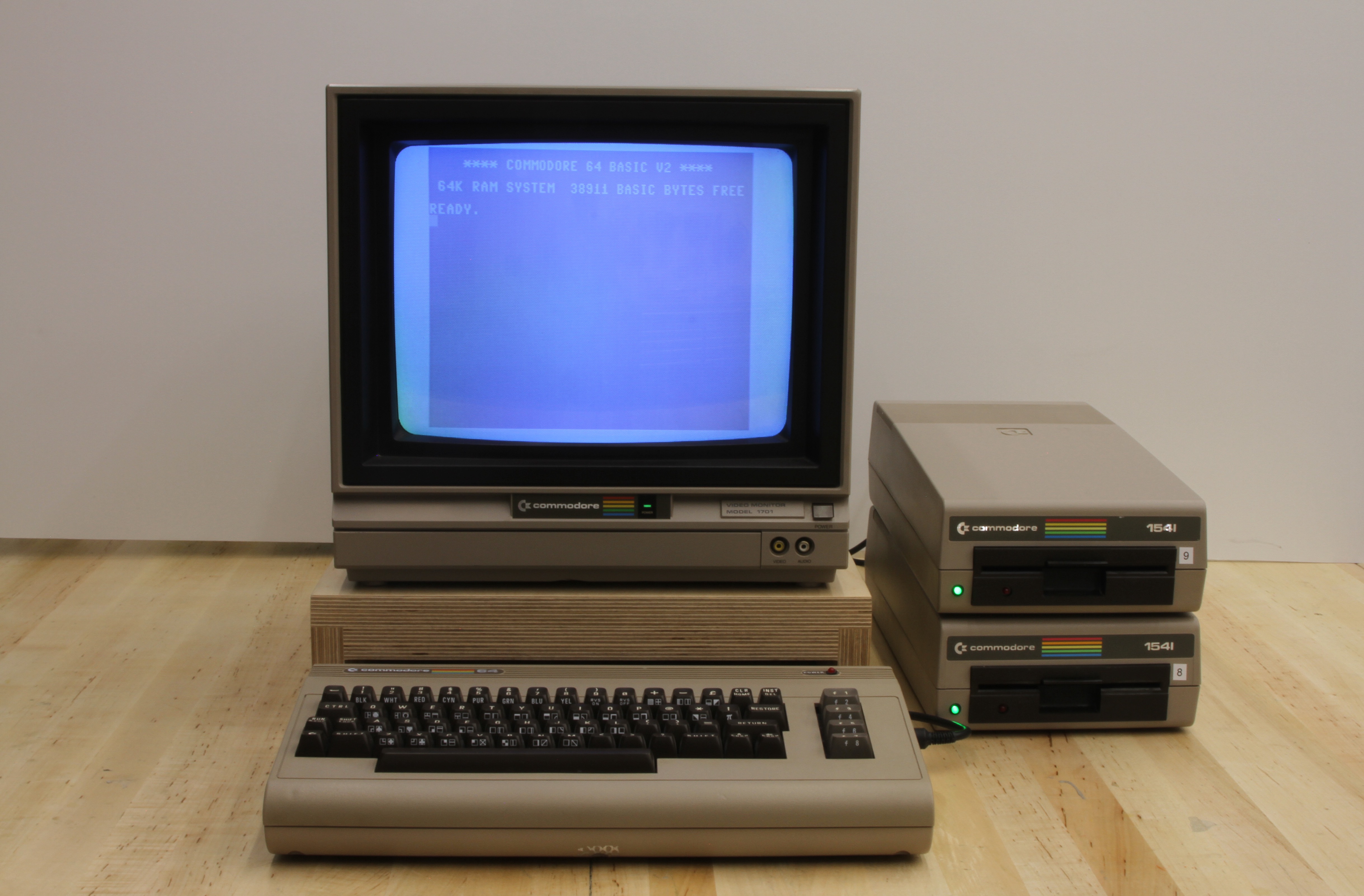
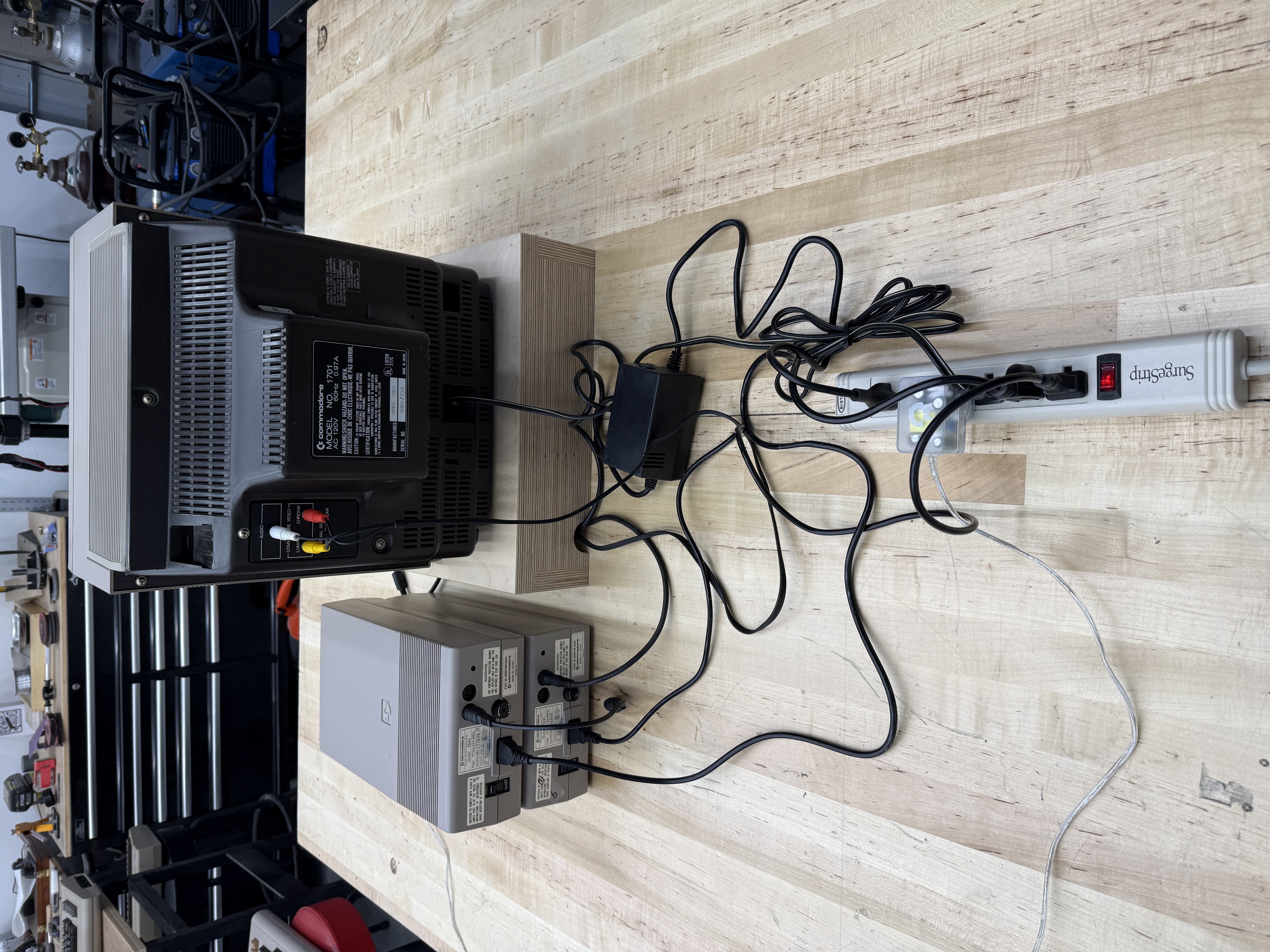
So when one of these turns up dead on a workbench, it isn’t an abstract repair. It’s the machine. And owning one wasn’t simple either. The full setup (monitor, brick, two 1541s, the snake’s nest of cables tying it all together) needed a whole power strip on the desk just to run the thing.
Coming back to it in 2017
I decided in 2017 to track one down and play around with it again. After buying several, it became clear I’d need to fix one of them rather than wait for a working unit to fall in my lap. So I picked the one in best condition. That one came from a guy in Boulder, Colorado, who literally left it on his front porch for me to pick up. I think I paid him $40.Knowing which board you have
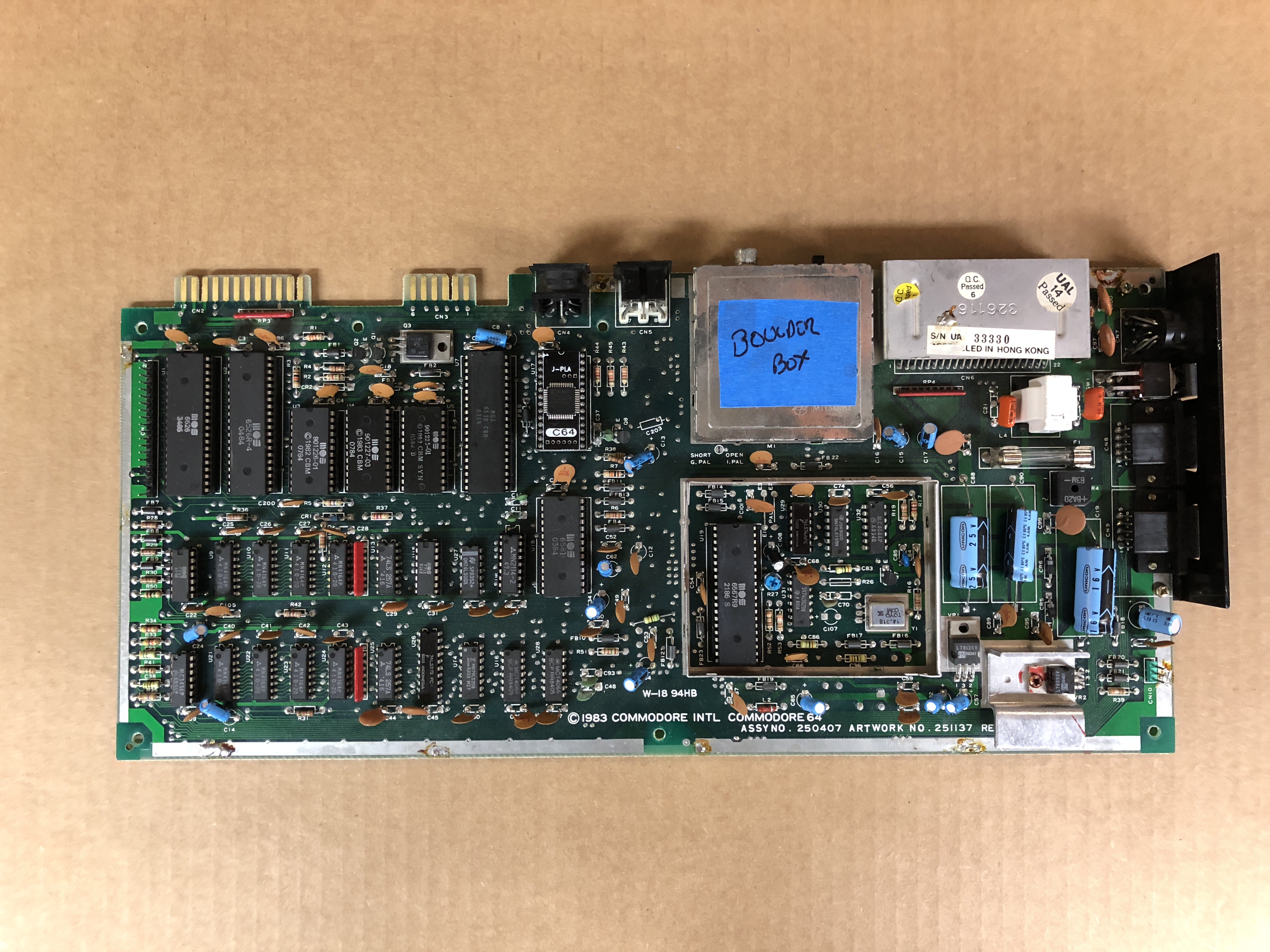
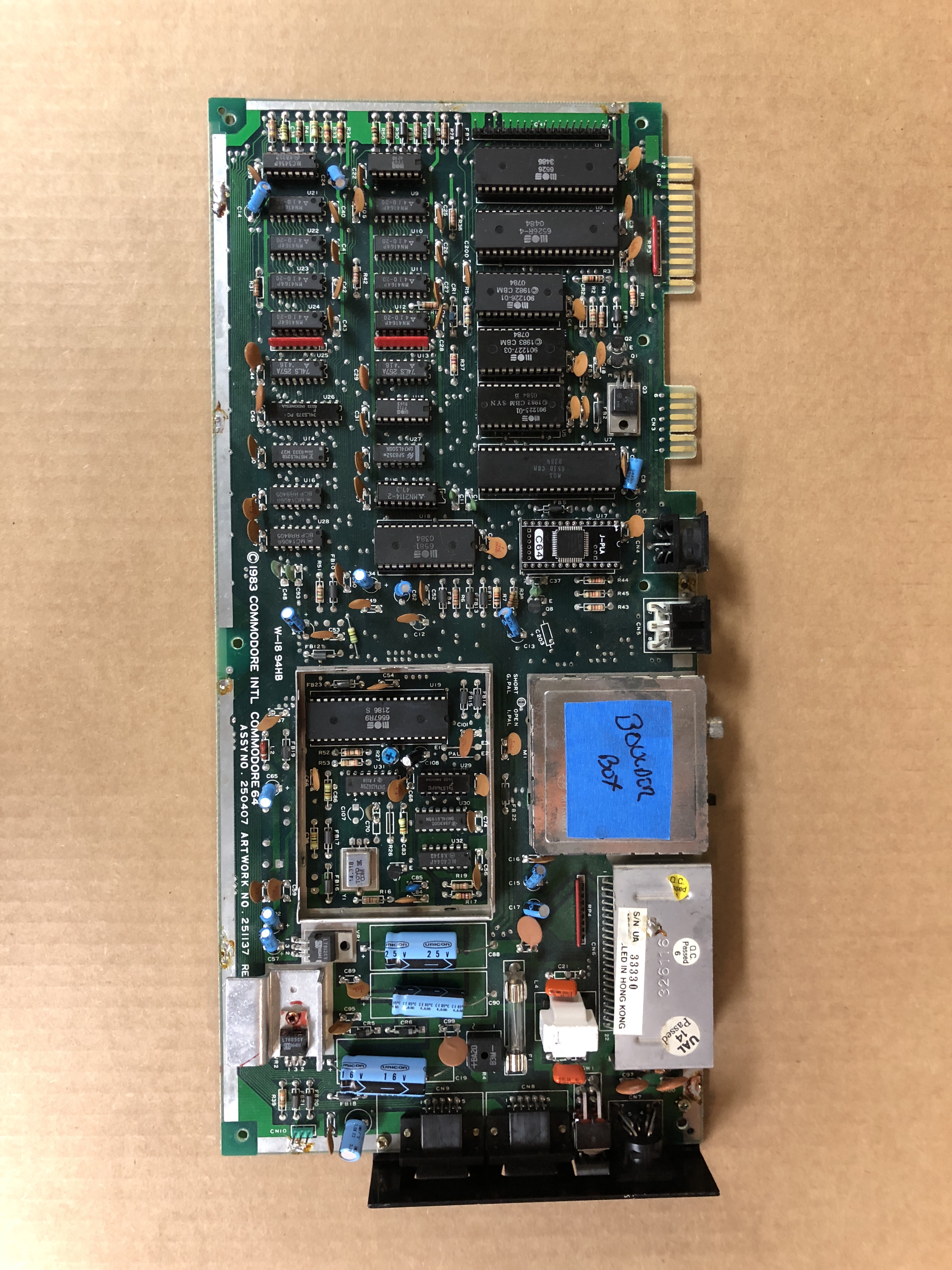
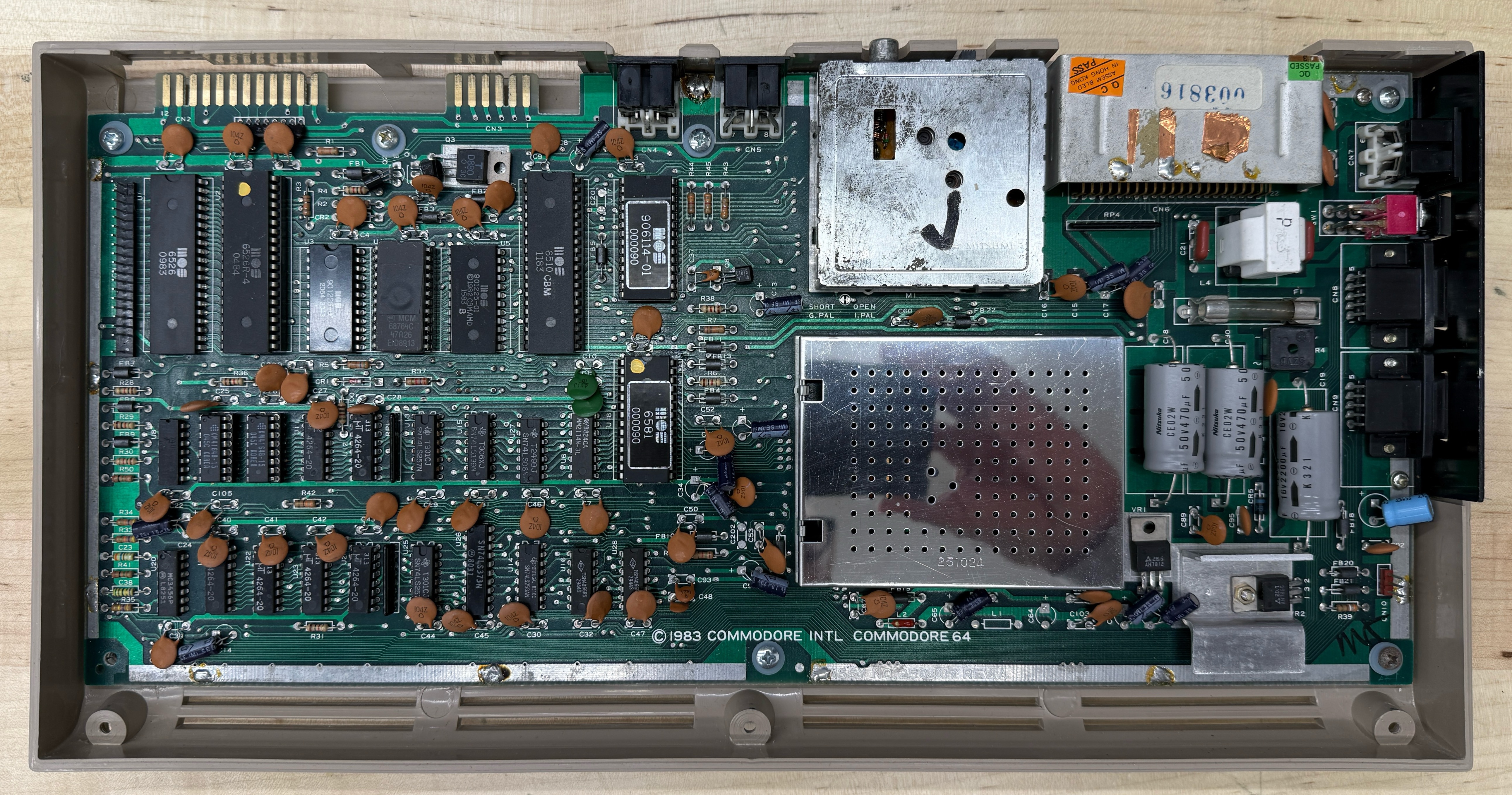
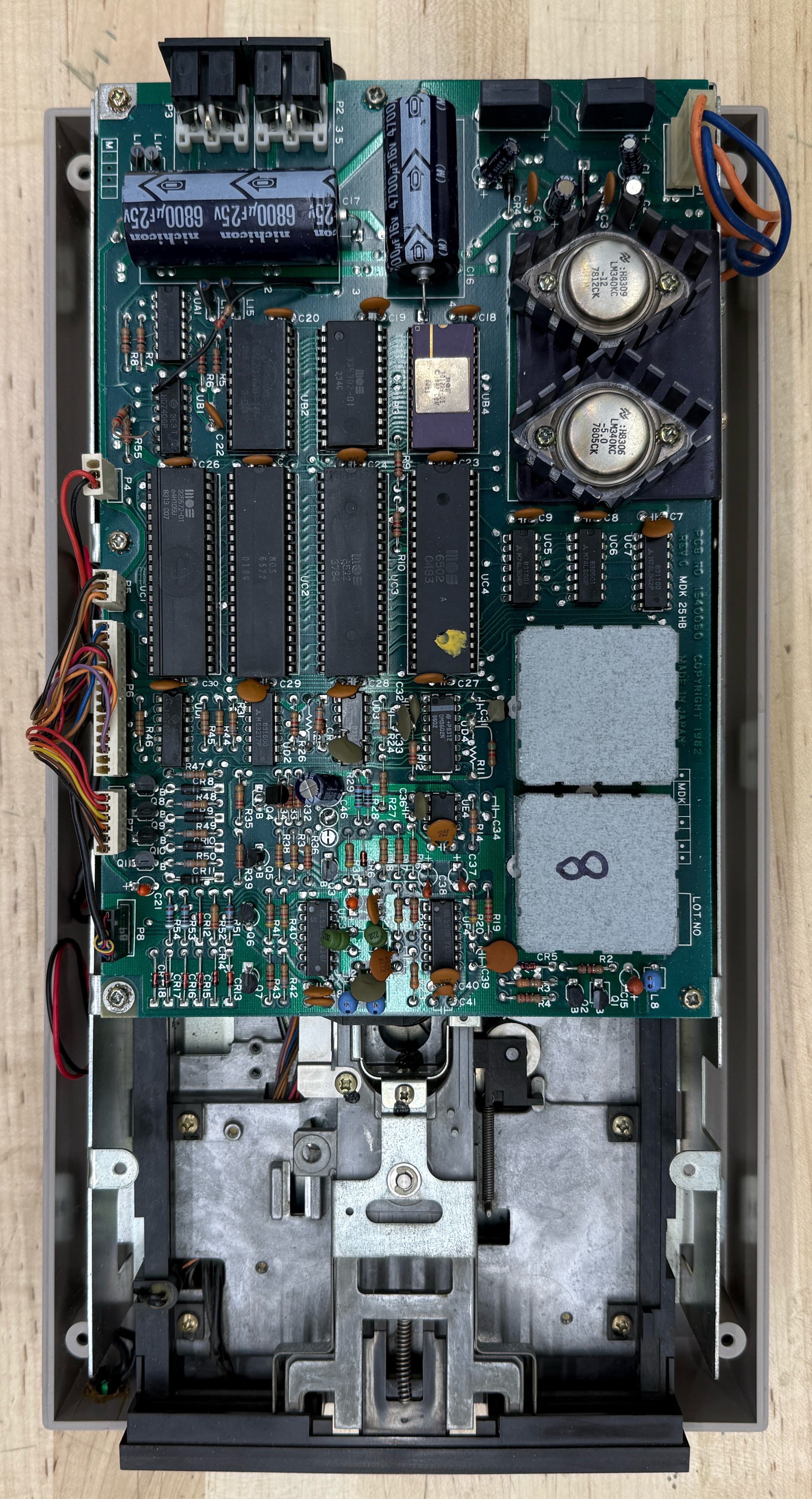
Before you can fix a C64, you have to know which one you have. Commodore made at least half a dozen distinct motherboards over the run, and the chip layout, the chip families, even the SID variant differ between them. The number you want is on the lower edge of the board, under the cardboard-and-foil shield on the earliest revisions or the metal can on later ones.
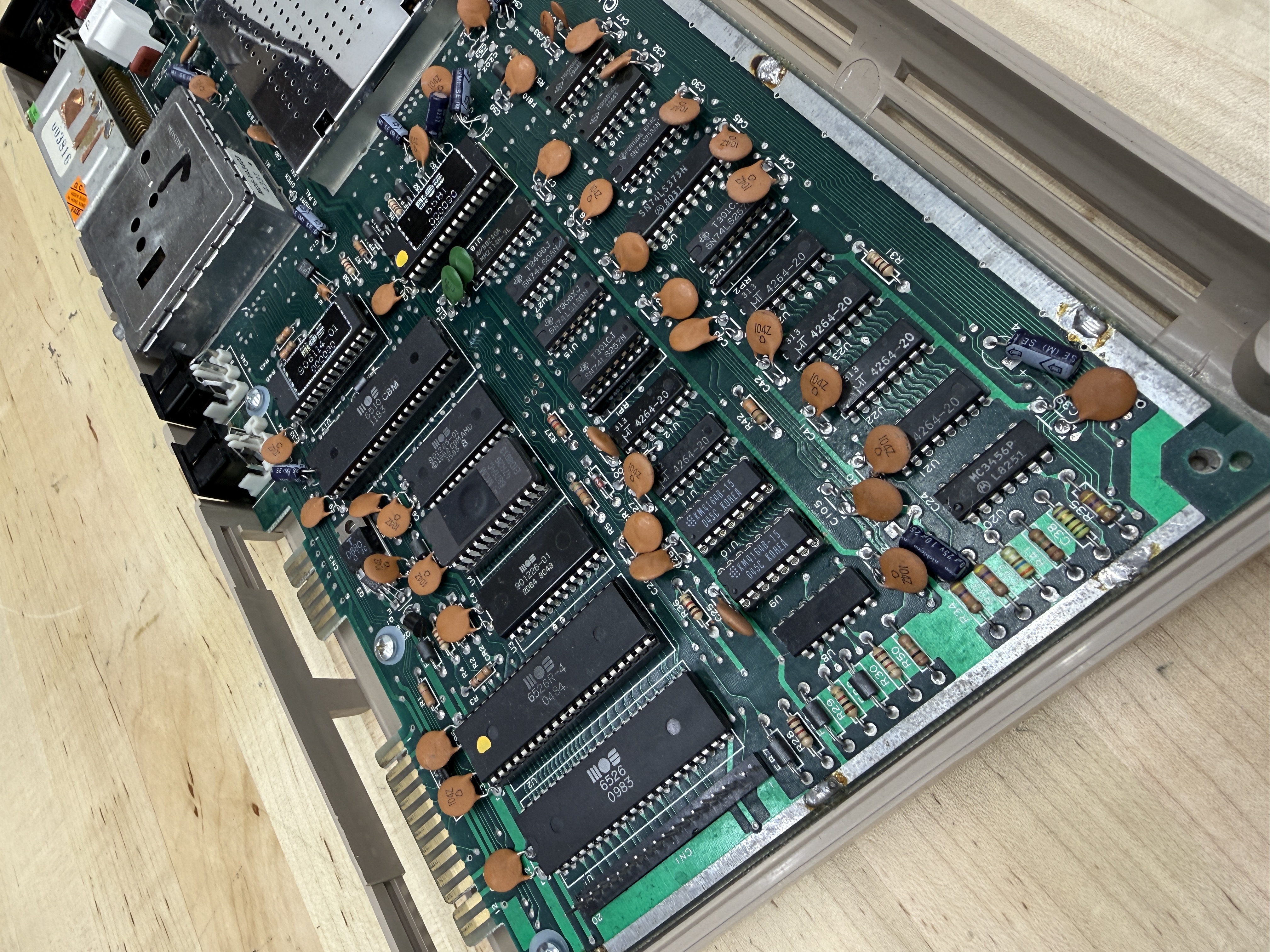
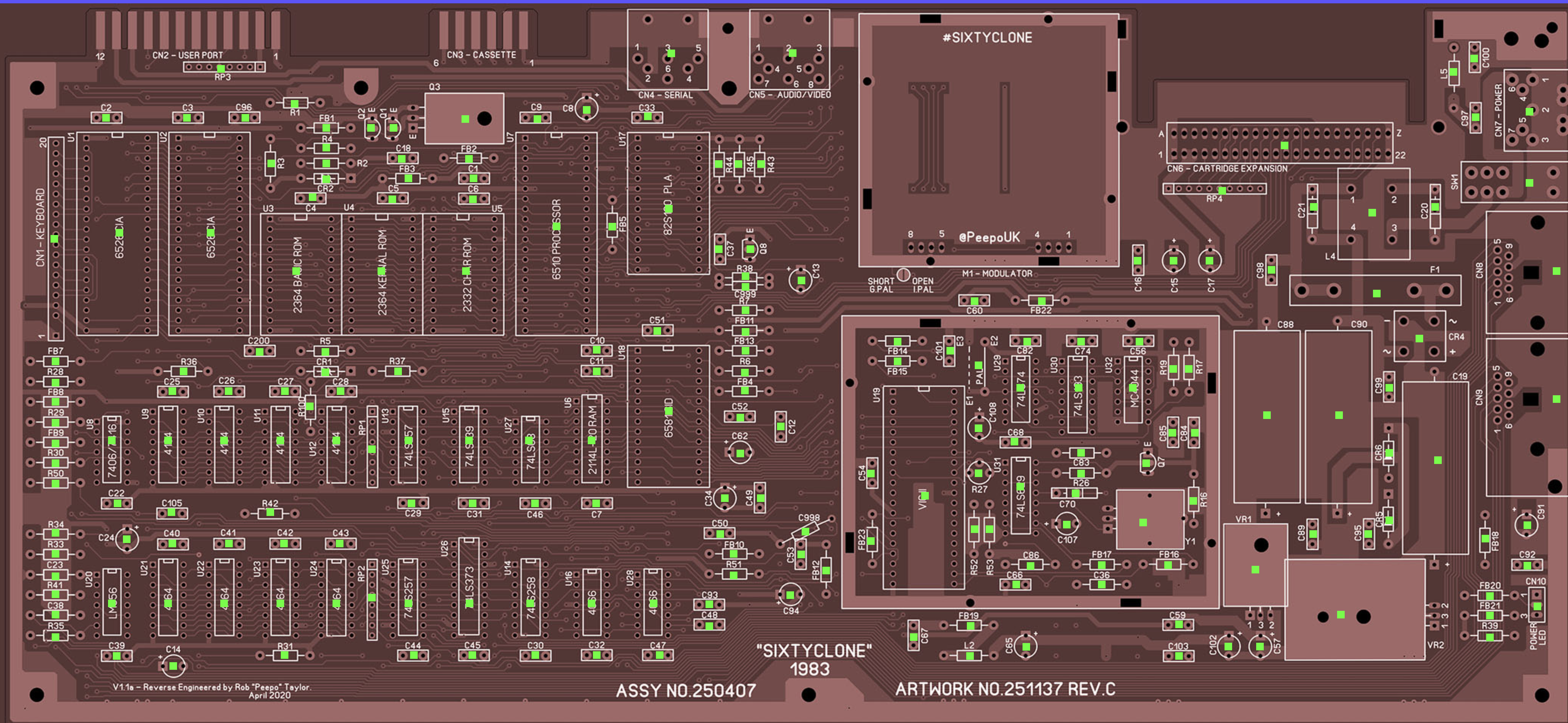
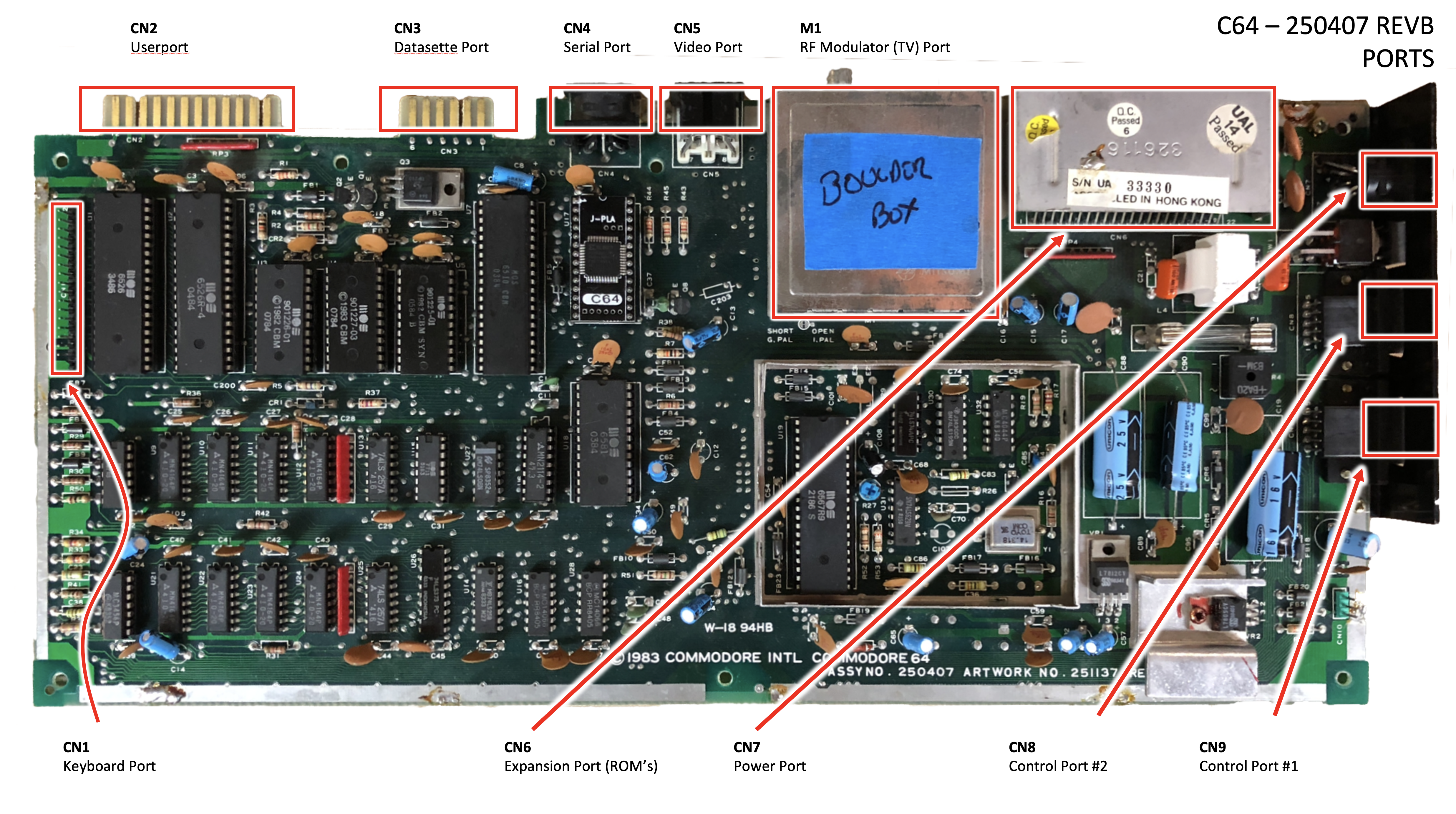
Mine was a 250407, schematic 251138, the most common breadbin board Commodore ever shipped, built from roughly 1983 onward. You can read the assembly number stamped right on the silkscreen in the photo. This was the board most American kids of a certain age had under their keyboard. PLA near the serial port, SID by the VIC-II, eight 4164 DRAMs across the bottom, and the two 6526 CIAs on the upper-left edge.
That number matters because the chip-vs-symptom guides you find online (the canonical one is Ray Carlsen’s, and I leaned on it heavily) reference each chip by its U-number, and the U-numbers move around between revisions. Once I knew it was a 250407, I had a map.
The dead-test cartridge
The single piece of gear that turned me from a guy staring at a dark screen into a guy who could actually do something was the dead-test cartridge, a Commodore service tool from the mid-1980s, originally shipped to authorized repair centers. There are actually two of them. The Dead Test (revision 781220) is the bare-bones one. It boots in Ultimax mode at $E000, ahead of the KERNAL ROM, runs a basic RAM check, and if no screen ever comes up it flashes the border in a pattern that points at the bad DRAM. The magic is that you only need a working CPU, PLA, and VIC-II for it to tell you what’s wrong — RAM, the KERNAL, BASIC ROM, and character ROM can all be dead and the cart still works.
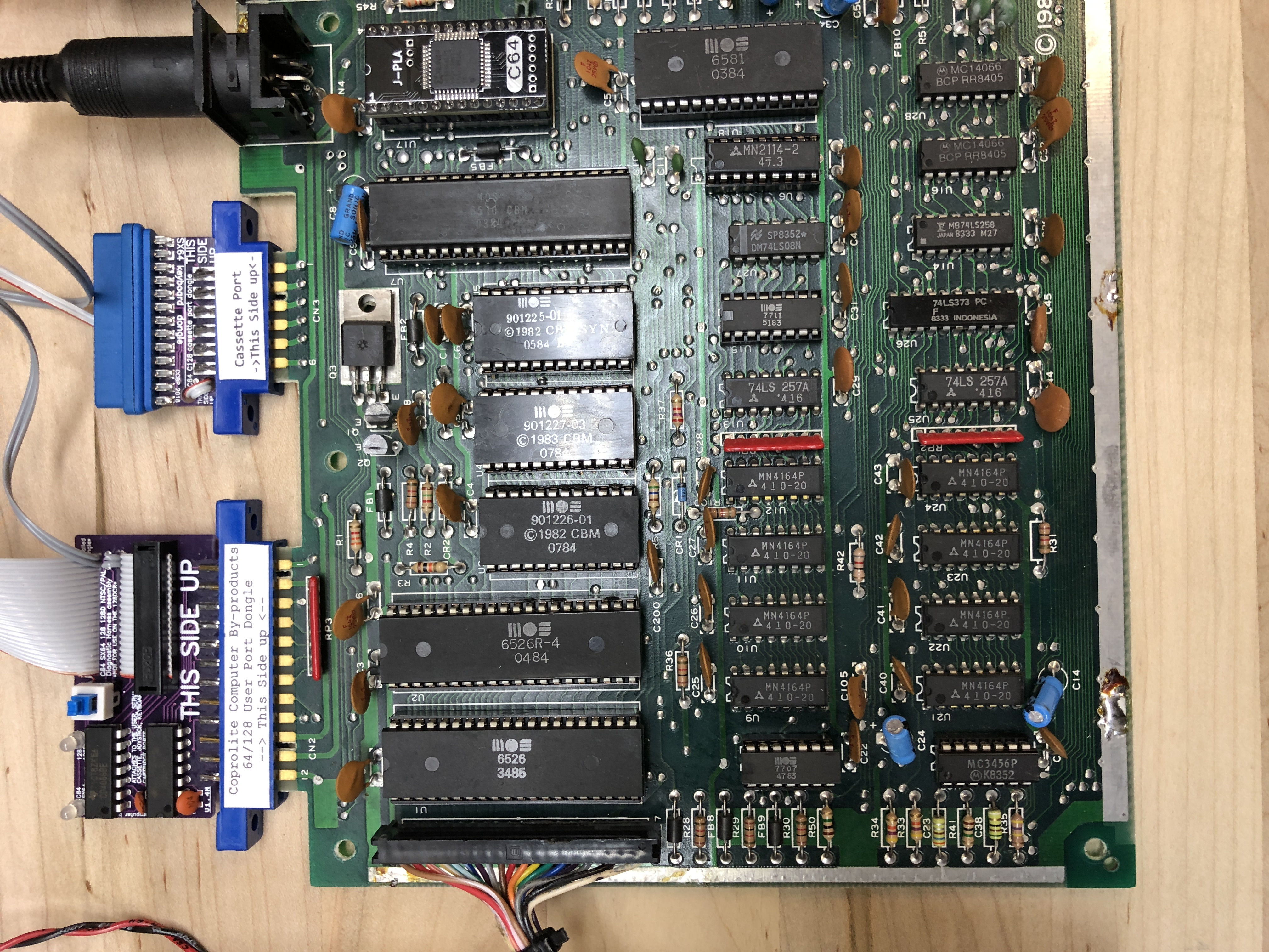
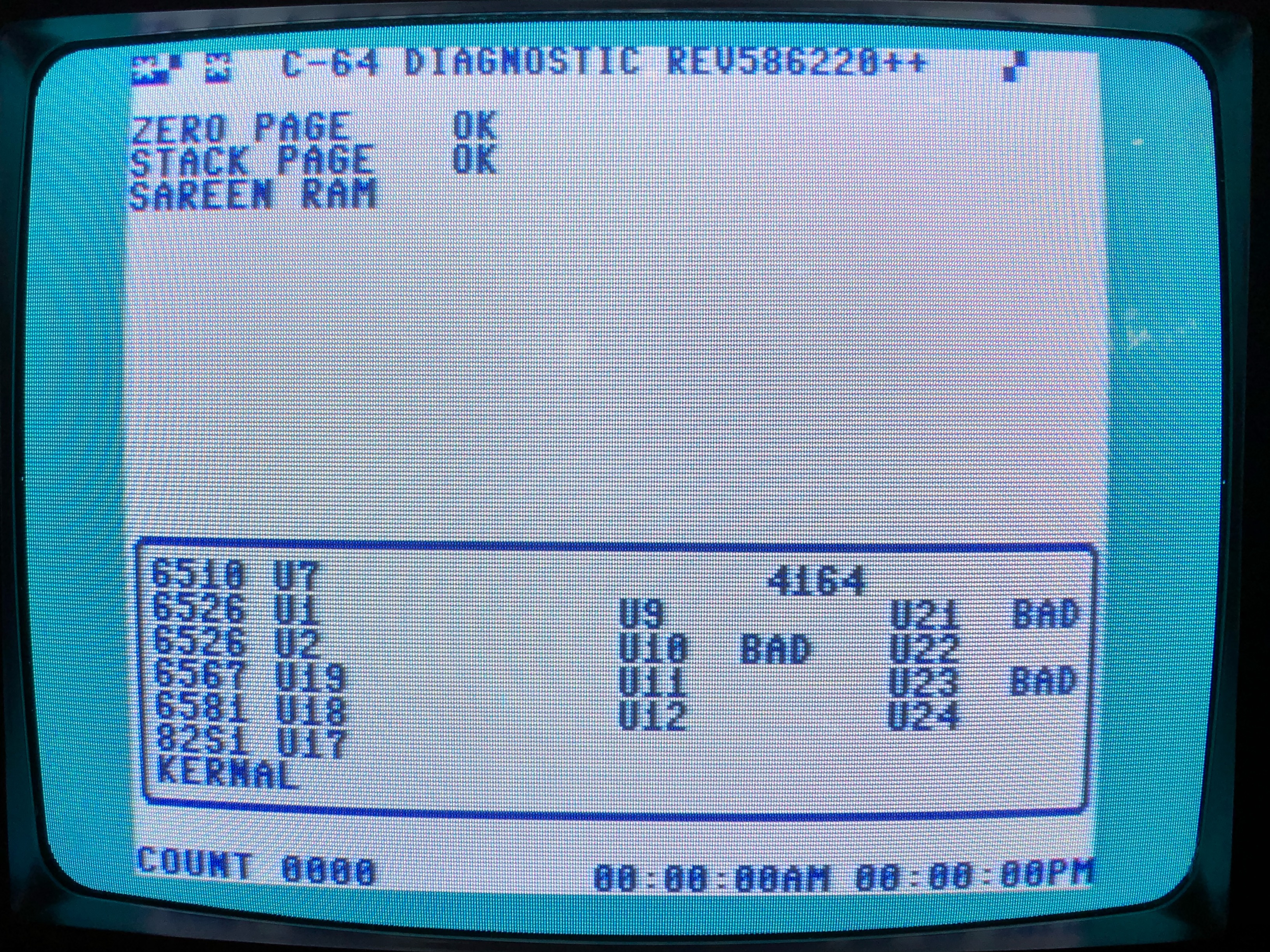
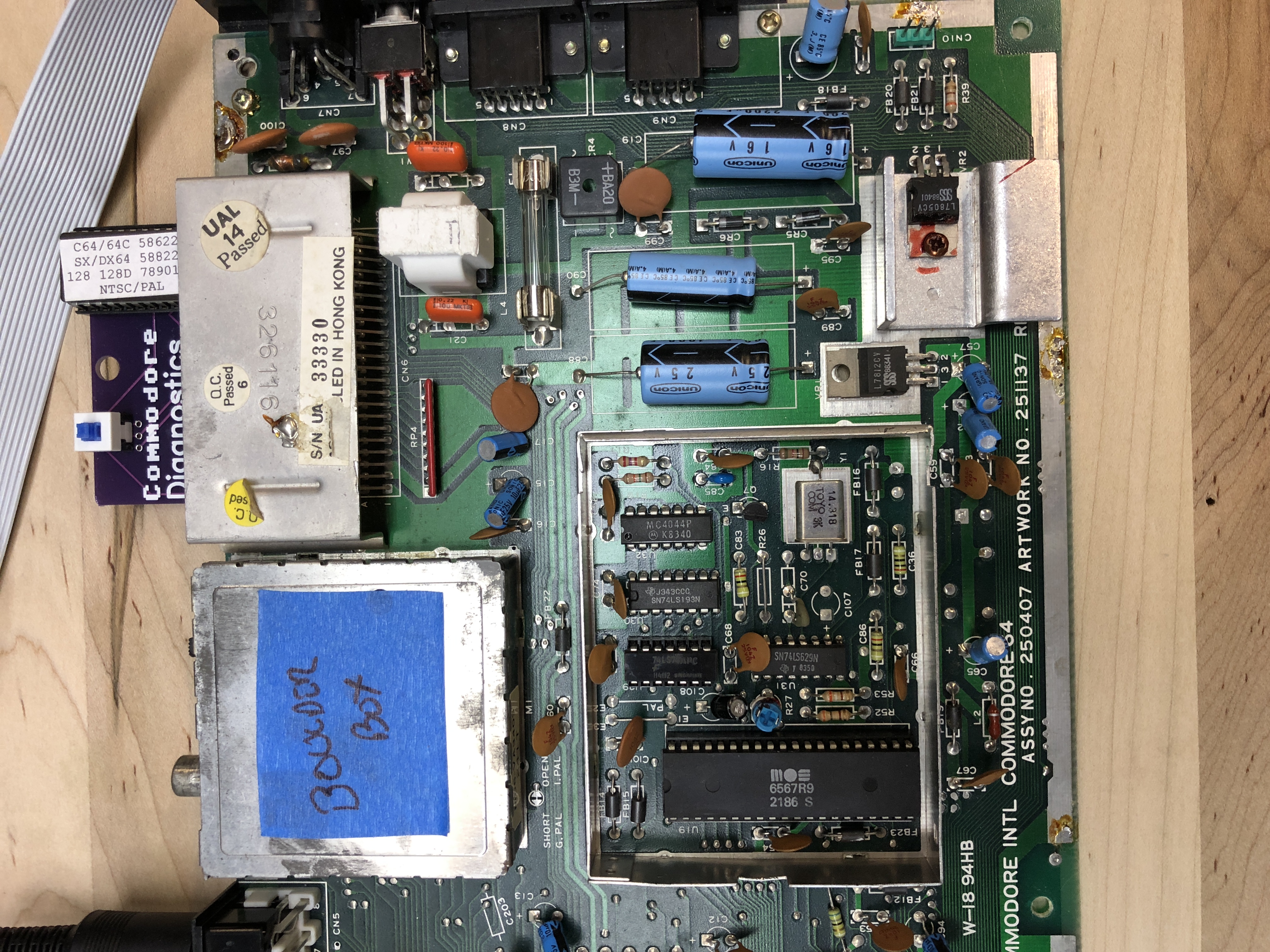
The Diagnostic (revision 586220) is the more thorough sibling: chip-by-chip RAM, ROM, CPU, CIA, SID, and VIC tests. It needs more of the machine working and uses the loopback harness on the user port and joystick ports to exercise the CIAs. That’s the one in the second photo. Modern reproductions usually ship both 781220 and 586220 on a single PCB and let you pick at boot. Mine is one of those, picked up off eBay for not much. Either way, the output points at chips by U-number, which you look up against Carlsen’s symptom guide. Between the two, you can usually go from “no picture” to “the suspect is one of these three chips” without a logic analyzer.
What needed replacing
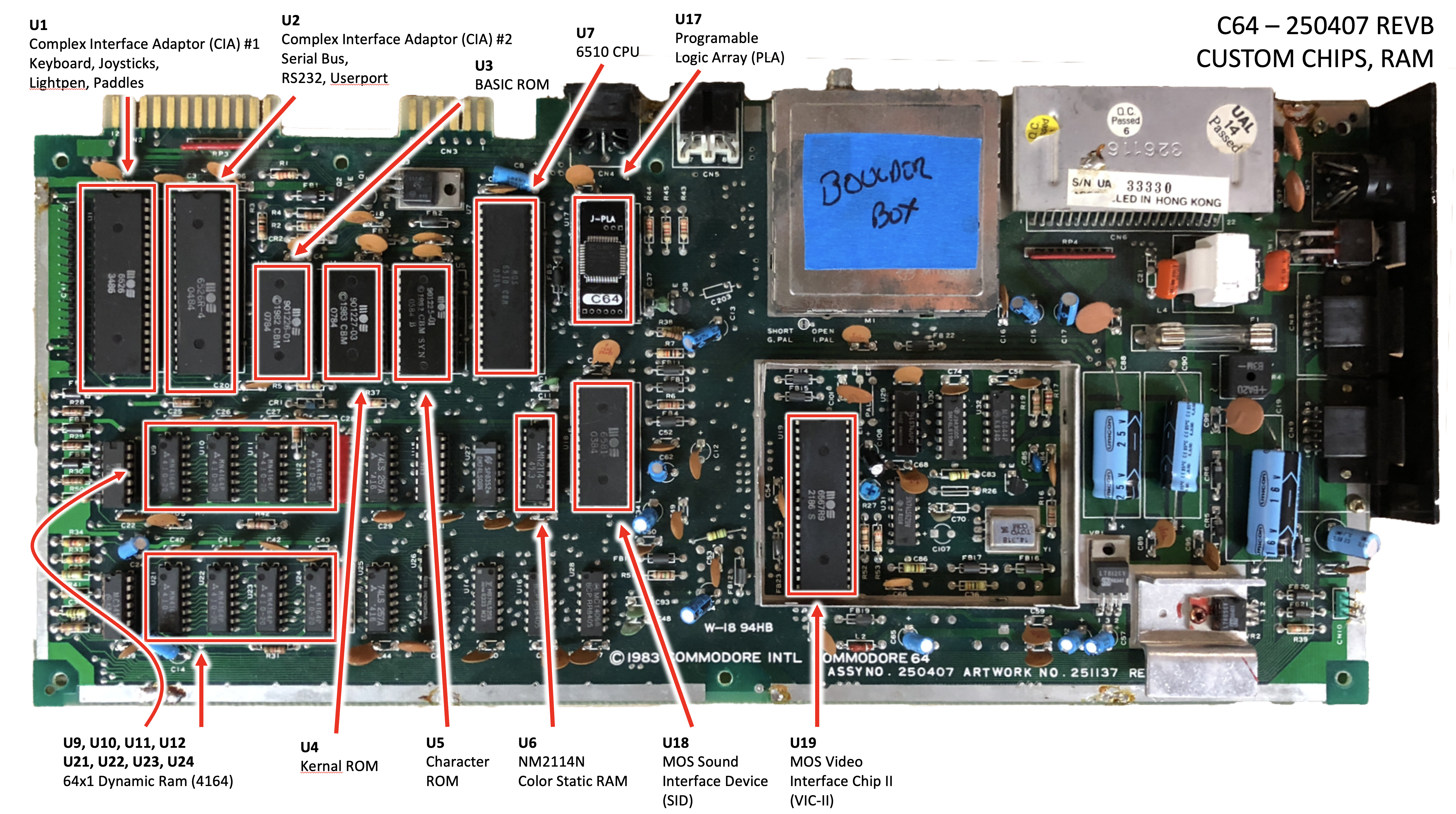
Working from my notes and the diagrams I made of the 250407, the breadbin needed work in the following spots. I’m using Ray Carlsen’s canonical U-numbering throughout. It’s the one that lines up with every C64 symptom guide on the internet.
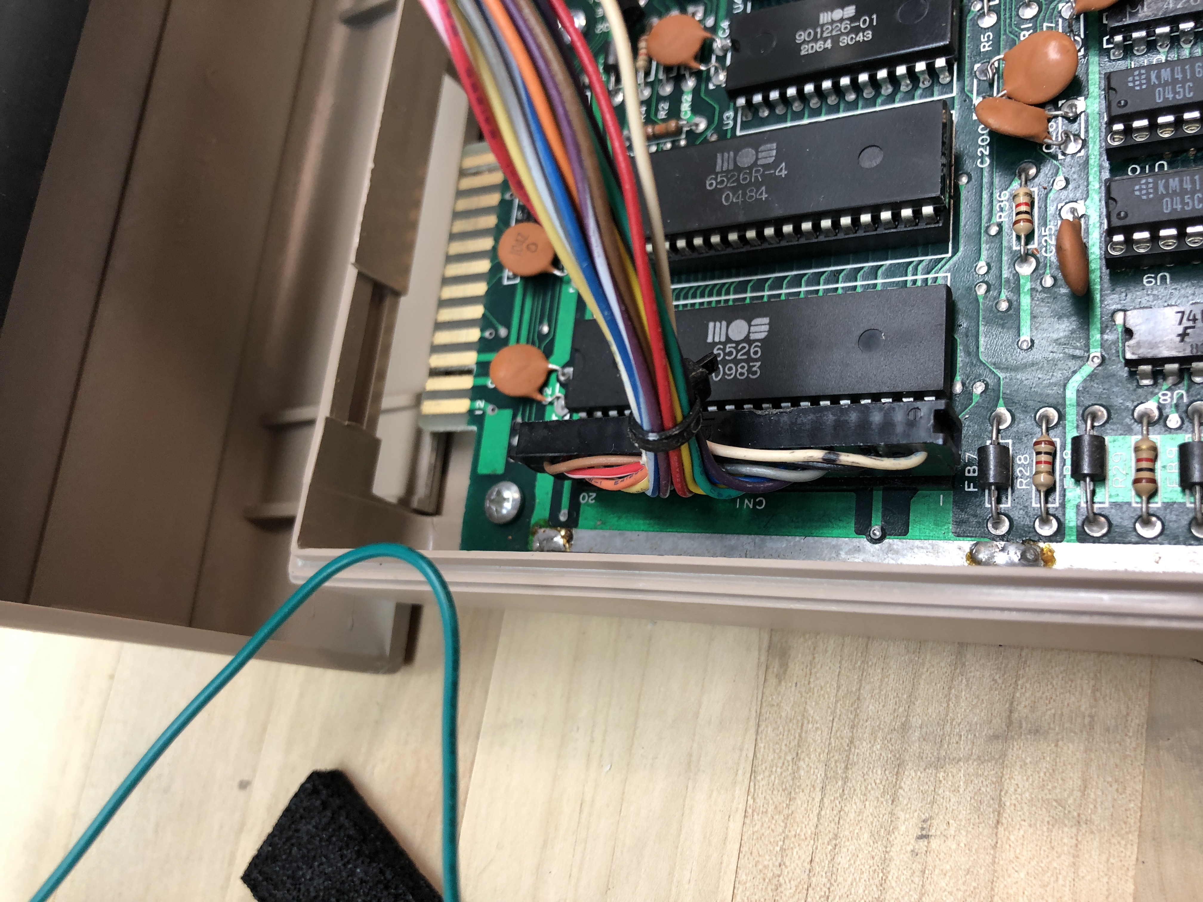
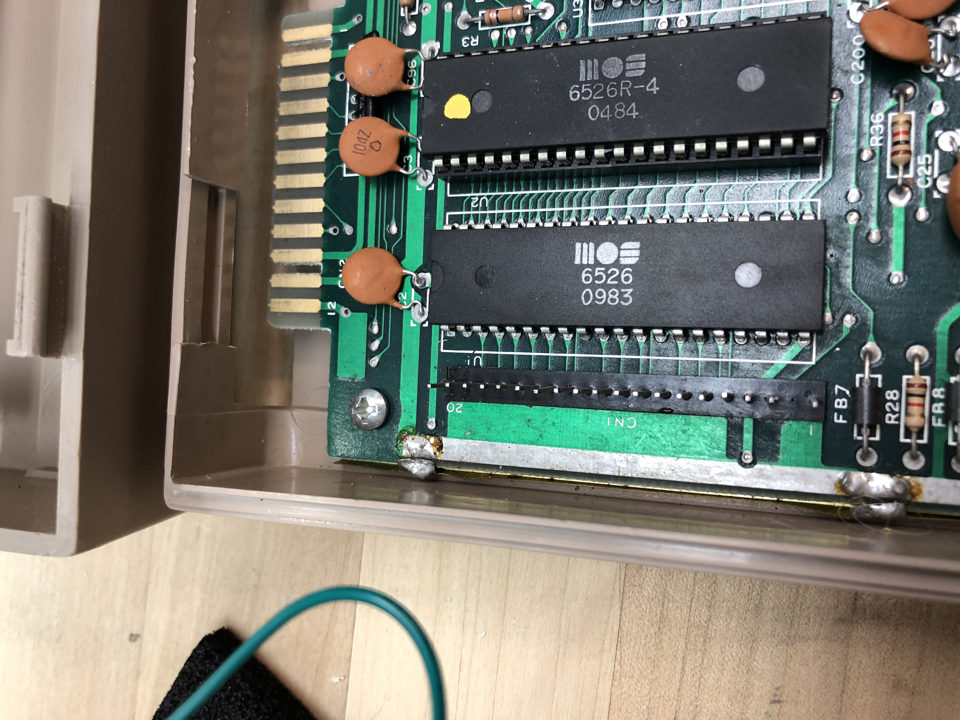
A note on method before the list. The dead-test cart is decisive about RAM and ROMs but its signal on the CIAs is softer. For those I socketed the suspect chip and its sibling so I could swap them between positions: if the symptom moves with the chip, the chip is bad; if it stays put, the problem is elsewhere. That’s why both CIAs ended up in sockets even though only one of them was actually bad.
- U1: CIA #1, the chip that owns the keyboard matrix and the joystick / paddle / lightpen control ports. Carlsen’s failure signature for this chip is “startup screen normal, but no cursor; no keyboard or control port access; cartridge works”, which is what I had. Confirmed by swap with U2 (the second 6526 CIA on the board, which handles the IEC serial bus, RS-232, and the user port; same chip, different job): the symptom moved with U1 to U2’s socket. Replaced U1; U2 itself was fine but stayed in its new socket.
- U5: the Character ROM. The symptom Carlsen describes is “normal startup border, but ‘garbage’ characters where startup page characters should be”, which is partial, scrambled characters on the screen instead of the clean READY. prompt. That matches what I saw.
- U6: the 2114 color SRAM. This is a small static RAM that holds per-character color attributes for the screen. A bad U6 produces flickering characters with shimmering colors.
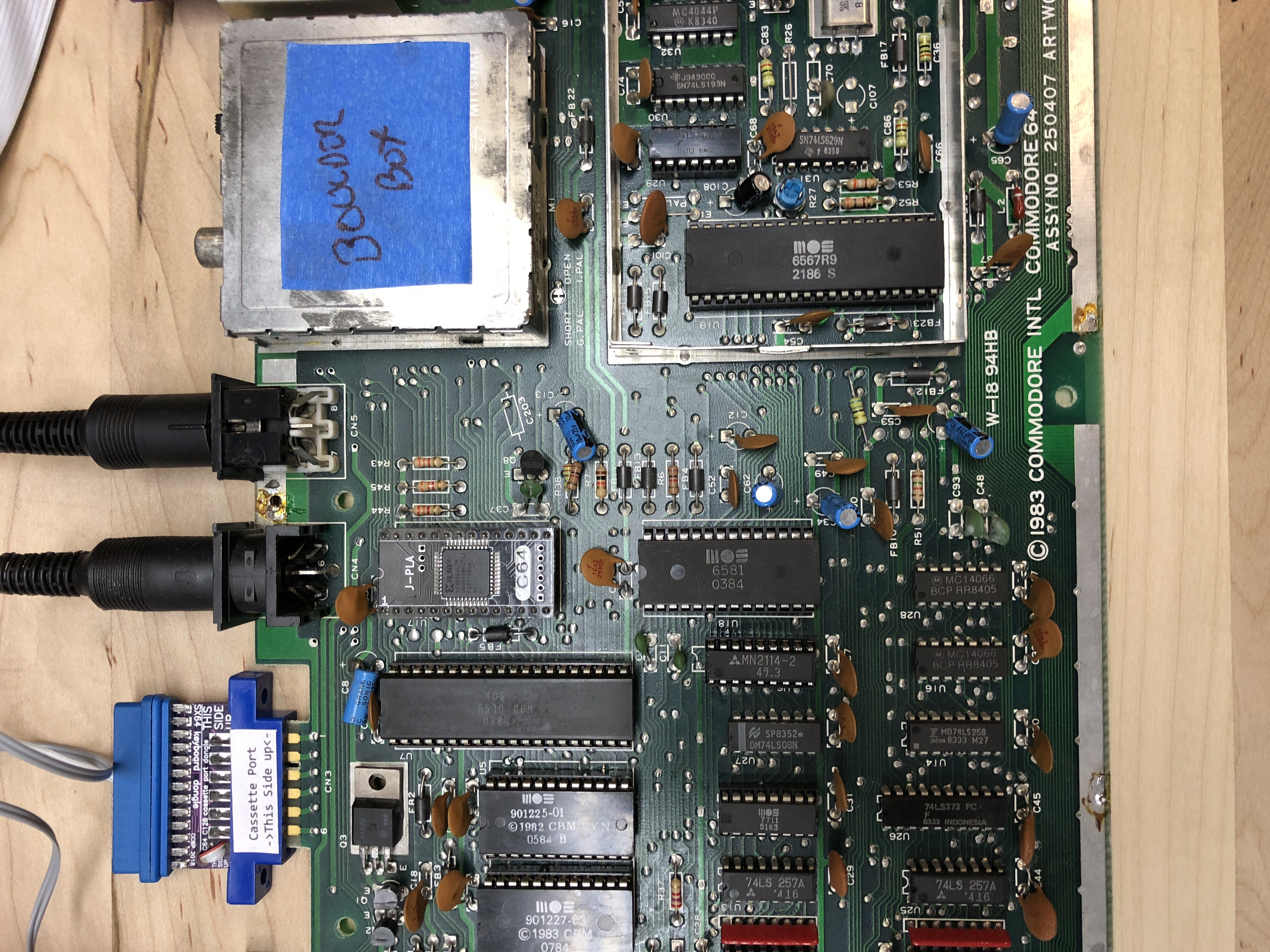
- U17: the PLA (the 906114-01 / 82S100). The PLA on a C64 runs hot all the time and is the most-cited custom-silicon failure on the platform. DRAM and CIA failures combined probably outnumber it, but the PLA is the one everybody warns you about first.
The 6581 SID at U18 tested fine and stayed put. The SID work I did on the Commodore side came later, on the SX-64, not on this breadbin.
Whenever I remove a chip, I generally solder a socket back in, then replace the chip. The 2114 is an 18-pin part and the position is a tighter fit than the 24- and 40-pin ROMs and CIAs around it. Every other replacement got a high-quality machined-pin socket, on the principle that the whole point of doing the work once was to make the next swap take ninety seconds instead of an evening.
Desoldering with braid
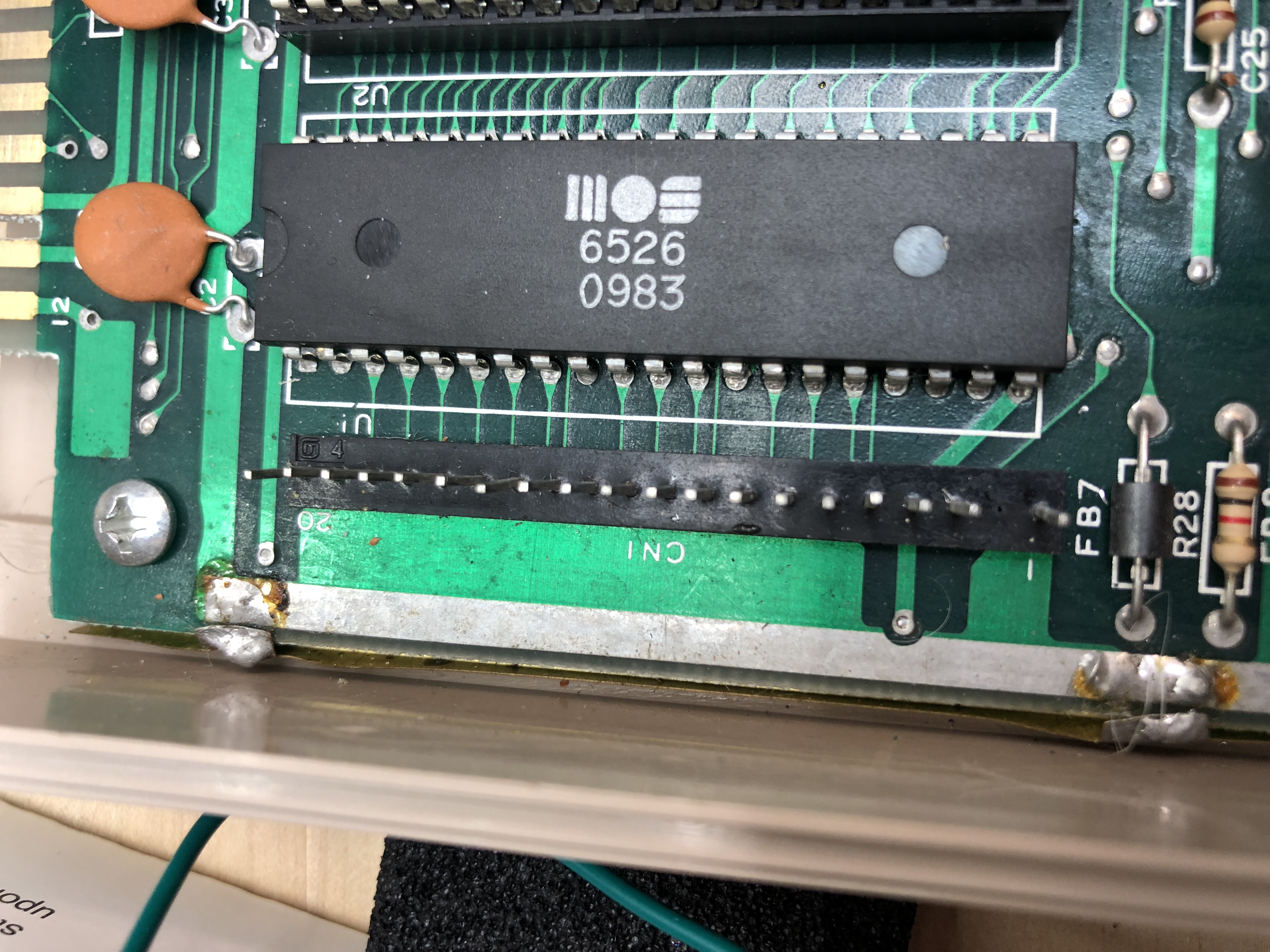
Here is where I have to be honest about my equipment in 2018, which is to say: I had a soldering iron, a roll of copper desoldering braid, and a lot of patience. No desoldering station. I did the entire CIA, ROM, and PLA swap with braid alone, working pad by pad, careful not to lift any traces.
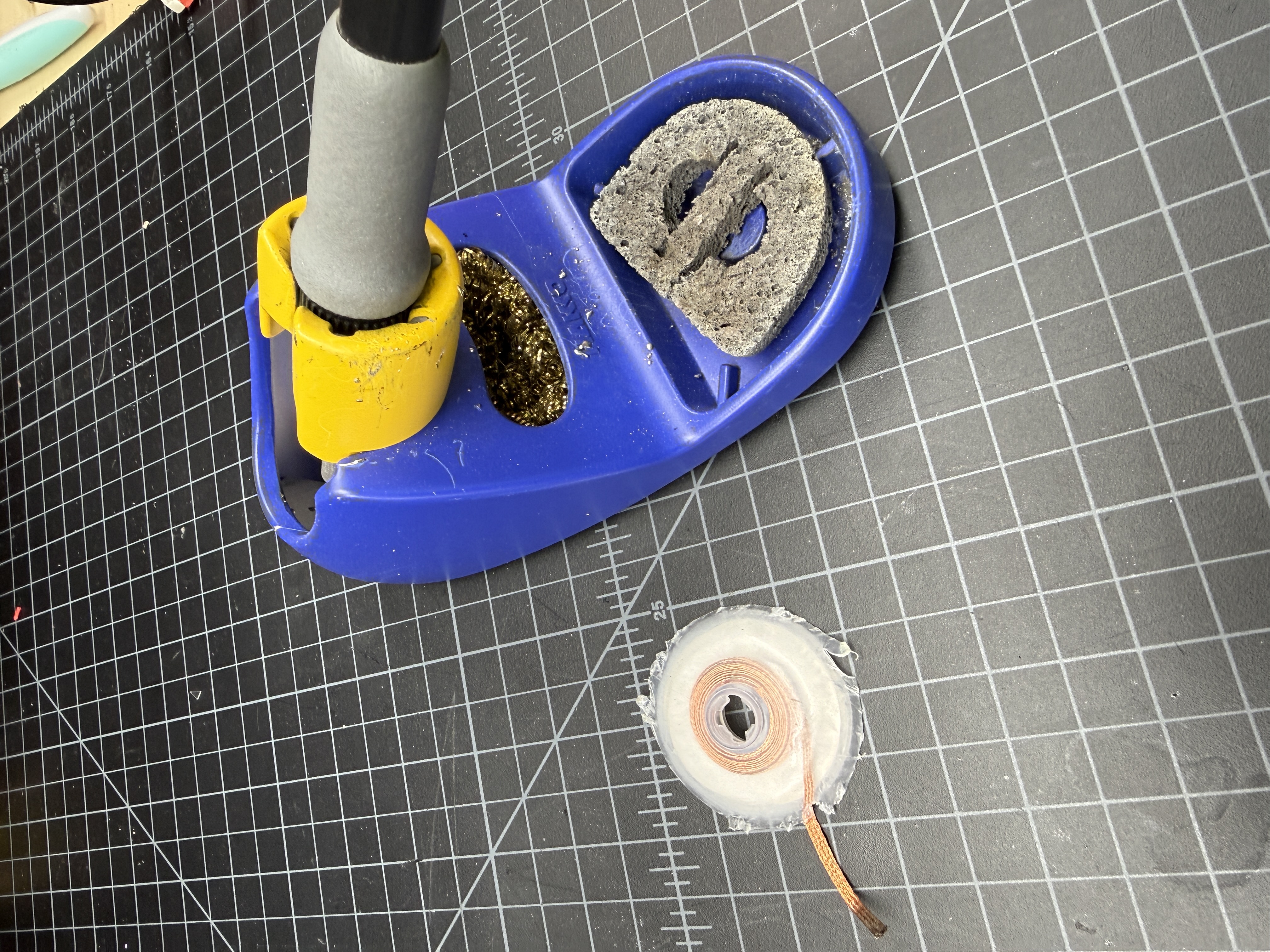
The C64’s saving grace is that the traces are chunky compared to anything from the later 16-bit era. There’s actual copper to work with. Even so, my conventional wisdom on these chips is: if the chip is a commodity chip, cut the legs off and remove the body, then desolder each pin individually. You’re a lot less likely to mess up the board. Now for a custom chip — the larger Commodore parts like the CIAs — you have no real choice but to meticulously desolder each pin one by one. Apply heat to one pin from the top, melt a little fresh solder onto the joint to wet everything (counterintuitive, but it gets the old solder flowing again), then hold the soldering iron tip on the braid and let the braid wick out the solder. Do this pin by pin, all 40 pins on a CIA, all 28 on a ROM. It is exactly as tedious as it sounds.
The check before lifting the chip is the most important step. Once you think you’ve got every pin clear, take a tiny flat-blade screwdriver and push on each pin from the side. The pins are generally bent out away from the body of the chip a bit, and when you do that, you will hear a small click as the pin separates from the outer side of the hole in the board. When you can wiggle each pin independently, you’re ready to start to wiggle the chip out. Don’t force it.
If I were doing this work today I’d reach for my desoldering station and pull the chips in a fraction of the time. There’s a separate desoldering-DIPs writeup coming as its own tech piece. This article is about what I did with the tools I had in 2018, and what I had was braid.
The power supply problem
One thing every C64 owner needs to internalize, ideally before plugging the machine in: the original Commodore “brick” power supplies have a famously bad failure mode. They can drift over-voltage on the 5V rail as they warm up, and when they do, they take RAM chips and sometimes worse along with them. A working brick today is not a guarantee of a working brick in twenty minutes.
I had bricks in the pile, and a couple of them tested fine cold, but I wasn’t going to trust any of them with a freshly-repaired board. I bought a replacement supply from Ray Carlsen at portcommodore.com/rcarlsen, a longtime member of the community who builds modern, regulated supplies that simply will not do the over-voltage trick. Money well spent. Carlsen’s site is also where most of the chip-vs-symptom write-ups I cite in this article come from.
A 1701 monitor
Around the time the board was coming back to life, I picked up a Commodore 1701 monitor on eBay. It arrived in a box maybe an inch larger than the monitor itself in every direction, no padding worth mentioning, and it was perfect. These things are built like tanks. I almost never see broken 1701s for sale, in part because I almost never see 1701s of any kind for sale.
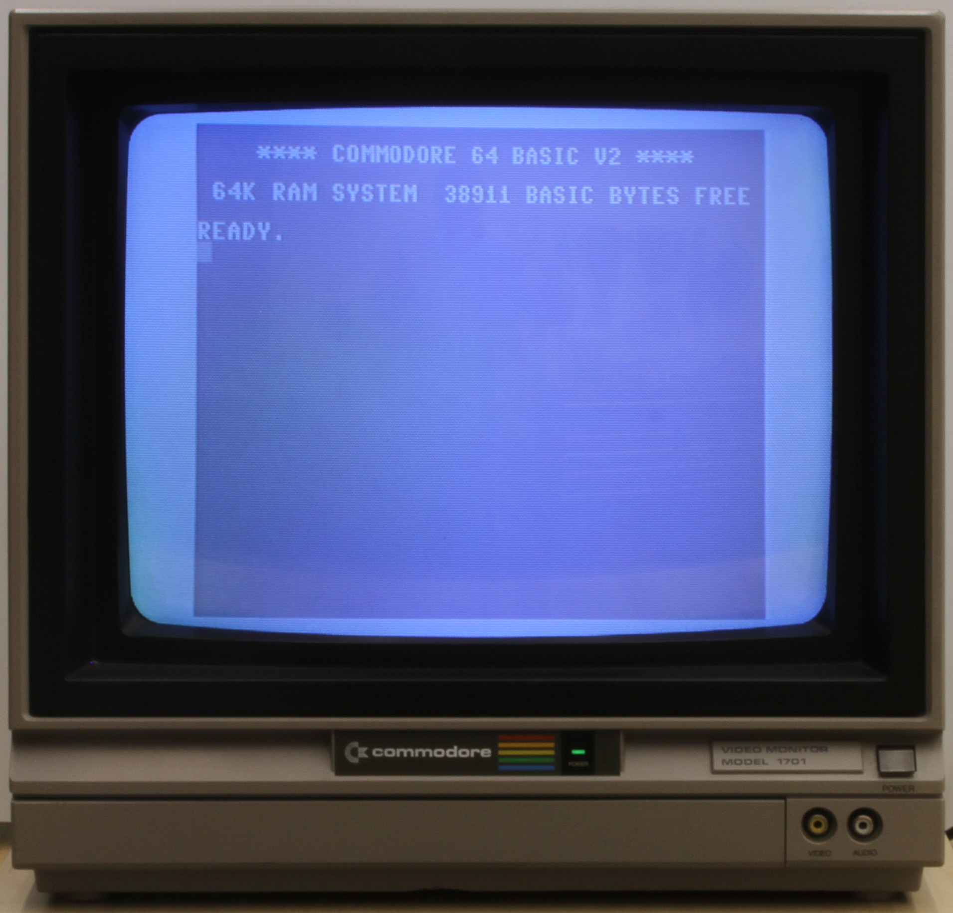
The chassis was built by JVC: the 1702 (and the 1701, which shares the chassis family) is essentially a debadged JVC C-1455 consumer TV with the tuner deleted and the inputs swapped for composite and S-video. Commodore reused the injection mold, which is why there’s a suspicious-looking notch above the rear inputs. That’s where the JVC’s rabbit-ears antenna used to snap in. The CRT itself was made by Hitachi. The official Commodore service manual covers the 1701 and 1702 as one document, which is itself a tell that they share the JVC chassis.
Two working 1541s from four
The drive situation took longer. I ended up sourcing four 1541s over a couple of months and parting them down into two reliably working units. Bad heads, bad ALPS mechanisms, one with a snapped door lever. The usual eBay 1541 catalog.
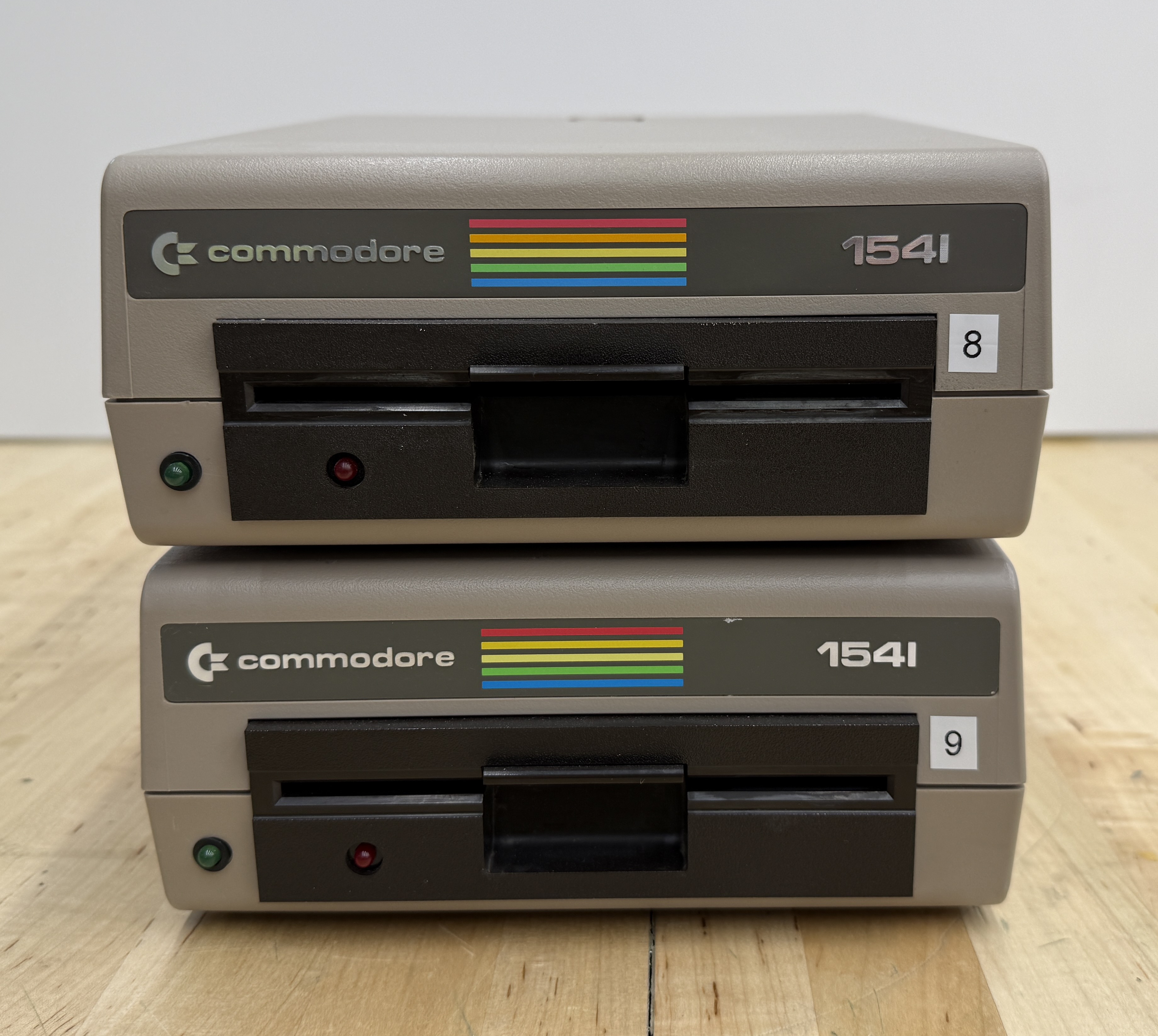
The only mod I made was the device number change. Every 1541 ships from the factory as device 8. If you want to use two on the same serial chain, the second one needs to be device 9, and the way Commodore intended you to do that was to pop the case, find a pair of solder pads on the controller board, and physically cut a trace.
There was a software workaround. You could send a memory-write command over the IEC bus to flip the device number in the drive’s RAM. The official 1541 user manual documents it, and a BASIC one-liner was enough to do it. But the change reset on every power cycle, so it never really replaced the trace cut as the way people actually did it.
You can be smarter about it: cut the trace, solder a small SPST switch between the pads, drill a hole for it on the back of the drive, and you’ve got a flippable 8/9 switch you can change any time. Fifteen-minute mod, fully reversible, and it’s faintly insane that Commodore didn’t ship it from the factory. I assume it was a parts-cost decision and a “most users only own one drive anyway” decision.
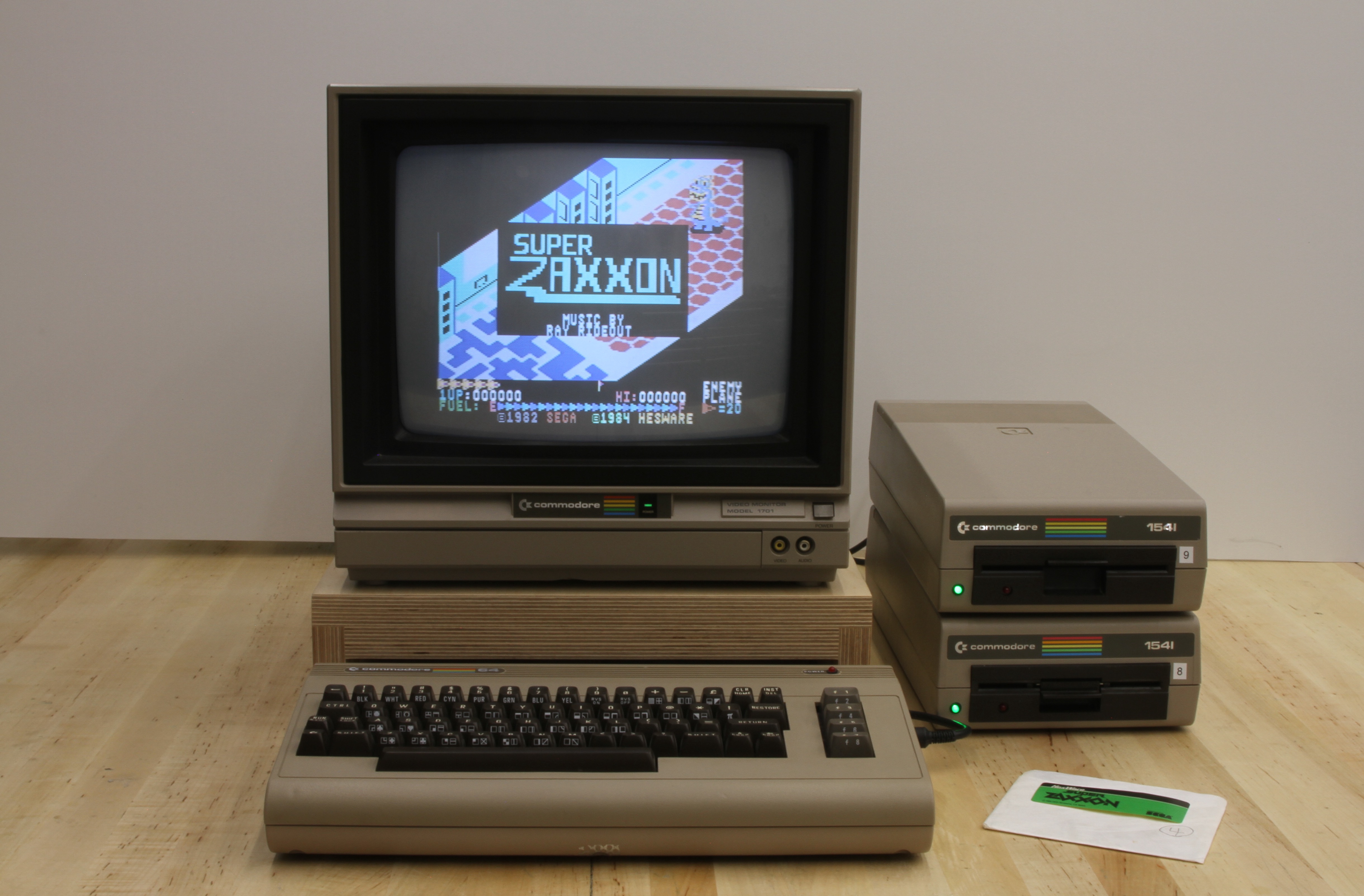
I didn’t bother with the switch. I cut the trace on one drive, made it permanently device 9, and that’s the 9 in the photo above. The other one is the default device 8.
What I'd do differently
A few things, in rough order of how much they would have saved me.
A real desoldering station. Braid is fine and braid will get the job done, but braid will also eat an entire afternoon for one CIA. The Hakko/Quick-style vacuum stations are a different category of tool. In practice I almost always use a combination of the desoldering station, braid, and flux to remove chips. It’s a bit of an art form.
A test rig. Adrian uses a known-good board with ZIF sockets at the major positions (CIAs, SID, VIC-II, PLA, ROMs) and ordinary sockets elsewhere, so he can drop a suspect chip in and confirm it’s bad in seconds rather than guessing across multiple variables (here he is doing exactly that on his test board). I should have built one on day one. I keep meaning to.
Better diagnostics. The dead-test cart is wonderful but it has limits. A logic analyzer or even just a decent scope on the address and data lines would have answered some questions I instead solved by chip-shotgunning.
Better notes at the time. The reason this article reads partly as a memoir and partly as a forensic exercise is that I didn’t write down enough while I was doing the work. Photos are great. Photos with timestamps and a paragraph of context next to them are better.
The longer version of all this lives in Bench Tools for Vintage Computer Repair: what’s actually on my bench now, in the rough order I acquired it, and what each piece of gear earned its place doing.
Modern replacements I'd reach for now
This article is what I did in 2018 with the parts that were obvious then. The community has built out a much richer ecosystem of modern drop-in replacements since, and a couple of them are already on the breadbin.
The cart in the expansion port on my breadbin is an Epyx FastLoad Reloaded, Jim Brain’s faithful modern recreation of the 1984 Epyx FastLoad cartridge, with the original ROM plus a few modern niceties on a small no-fuss board. It does the one thing it’s supposed to do, roughly 5× faster LOAD off a real 1541, without touching anything else in the system. Plug it in, leave it in, forget it’s there.
The community’s other answer to slow loading is JiffyDOS, a replacement KERNAL ROM in the C64 plus a matching one in each 1541. Same order-of-magnitude speedup, deeper integration, but the install requires swapping every ROM in the chain. I’m not in that much of a hurry. The Epyx cart is enough.
For drive emulation, if I ever needed to retire the real 1541s, there are three options. SD2IEC is the cheap, ubiquitous SD-card-on-IEC option, fine for most non-protected software. Pi1541 is the cycle-accurate Raspberry-Pi-based emulator that fools the things SD2IEC can’t. The Ultimate II+ cartridge is also Gideon Zweijtzer’s work, by the same engineer behind the FPGA in the new full-machine Commodore 64 Ultimate; it goes a step further than SD2IEC or Pi1541, packing 1541, REU, datasette, and cartridge into one cart off a microSD. I run real 1541s so I haven’t reached for any of these, but all three are on the desk of every serious C64 owner I know.
The PLA in mine is already a modern replacement, a J-PLA I got from Retro8bitShop. Real PLAs are among the most-faked chips on eBay, so a known-provenance modern part is often safer than a “real” one off eBay.
The other custom silicon has its own modern parts now too. The SID at U18 has several drop-in replacements: SwinSID Nano, ARMSID, SIDKick Pico, and FPGASID. The 6581 in my breadbin still works so I haven’t had to swap it, but I put an ARMSID in the SX-64, and it’s indistinguishable from a working original on anything I can hear.
The VIC-II at U19 now has Kawari, an FPGA replacement that wasn’t really around when I did this work. The CIAs at U1 and U2 still don’t have a clean drop-in. The pool of working chips harvested from parted-out boards is what you reach for, which is why I socketed both of mine.
None of this changes what’s on the bench today. The breadbin still has its ‘83-vintage MOS silicon, its Epyx cart, and its Carlsen brick. But if any of the custom chips fail, I know what’s going in next.
Why this one mattered
A broken breadbin, a roll of braid, a Carlsen brick, a tank of a monitor, and a pair of 1541s with one trace cut I shouldn’t have had to cut. That’s the parts list. The thing I didn’t have on the parts list, and the thing I actually got out of it, was the conviction that these machines are fixable. The failure modes are documented, the chips are sourceable, and the only real prerequisite is being willing to do something tedious carefully.
Every machine since then has followed the same flow: identify the patient, follow the symptom map, swap the part, socket it on the way back in. The SX-64, the PETs, the Apples — all of them.
The breadbin still boots. For what this hardware looks like rebuilt in modern silicon, I wrote a separate piece.
Useful Documents
C64 Diagnostic Instruction and Troubleshooting Manual (PDF) — Commodore’s official diagnostic manual (part 326070-01). The factory reference for board-level fault isolation, dead-test cartridge procedures, and chip-by-chip symptoms — the deeper companion to Carlsen’s symptom guide.
C64 Service Manual (PDF) — Commodore’s official service manual for the breadbin. Schematics, board layouts, parts lists, and disassembly procedures — the reference for any work past chip-swapping.
How to Identify Your C64 Board — Ray Carlsen’s guide to identifying which of the half-dozen breadbin motherboard revisions you have. Walks through locating the assembly number stamped on the board and what each revision means for repair.
Commodore 64 Socketing Parts — Mouser part numbers for the four DIP-socket sizes used on a 250407, plus a note on the 2114 color SRAM at U6.
1540/1541 Service Manual, November 1985 (PDF) — Commodore’s official service manual for the 1540 and 1541 disk drives. Schematics, alignment procedures, and component-level repair — what you reach for when an ALPS mechanism is misbehaving.
1540/1541 Single Disk Technical Reference Manual (PDF) — Programmer-facing reference for the 1541. DOS commands, disk format, drive internals, and the 6502 firmware that lives inside — the deeper how-it-works companion to the service manual.
1540/1541 Service Manual, preliminary edition, January 1985 (PDF) — Earlier preliminary edition (part 314002-01). Mostly superseded by the November 1985 manual but useful for cross-referencing the earlier 1541 board revisions.
1541 Chips vs. Symptoms — Ray Carlsen’s chip-vs-symptom guide for the 1540 and 1541 disk drives. The 1541 companion to his C64 chip guide — which IC failure produces which fault, for both ALPS and Newtronics mechanism boards.
1541 Diagnostics — Ray Carlsen’s 1541 troubleshooting guide. Power-up diagnostics, common failures, and alignment procedures — the practical step-by-step companion to the chip-symptoms list.
Commodore DOS Quick Reference — The handful of 1541 DOS commands that come up over and over: load, save, format, delete, reset. The cheat-sheet for talking to a 1541 from a C64 BASIC prompt.
Sources
- Ray Carlsen’s chip-vs-symptom guides at portcommodore.com/rcarlsen — the canonical reference for “what does a bad U-whatever look like.”
- Dave Farquhar’s Commodore 64 motherboard revisions — the clearest single rundown of which board is which.
- Dave Farquhar’s Exploring the Commodore 1702 Monitor — background on the JVC chassis lineage shared by the 1701 and 1702.
- Commodore 64 Community Resources — the people, vendors, and archives that keep this platform alive — Carlsen, Adrian, Jim Brain, Gideon, CSDb, Lemon64, and the rest of the bookmark list.
- Adrian’s Digital Basement on YouTube — the apprenticeship.
A note on Ray Carlsen
Most of this restoration leaned on Ray Carlsen’s site in one way or another. The replacement power supply still running my breadbin is one he built. The chip-vs-symptom guide I checked every U-number against is one he wrote. The 1541 troubleshooting steps linked above are, step by step, his.
Carlsen has been repairing Commodore 8-bit hardware professionally since the 1980s, and his site is the closest thing the community has to a single canonical reference for it. It covers the PET, VIC-20, C64, C128, the 1540/1541/1571/1581 disk drives, the 1701/1702 monitor family, and most of the CMD peripherals on top of that, each with chip-symptom guides, schematics, service notes, and his own repair histories. He also designs and sells modern replacement power supplies and Computer Savers, which is where my breadbin’s PSU came from.
If you have something Commodore on the shelf that doesn’t boot, that site is where you start.
Gallery